


Troubleshooting
Maintenance
6Ć50
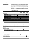
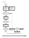
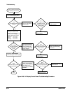
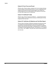
This procedure checks the
A2 Display Control board.
Turn the Scale Illumination
control while watching the CRT.
No
Yes
Does
the scaleillumination
change?
Disconnect the cable to
J80 on the A2 Display
Control board.
Is
the voltage on pin
12, W66 on the A3
Display Driver board
approximately
+15V?
No
Yes
Replace the A63 Power
Supply module.
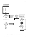
Measure the voltage on the
center pin of each of the
control potentiometers.
Check for the voltages below
while rotating the controls.
Readout 0 to +5.2V
Focus 0 to -5.2V
Intensity 0 to +5.2V
No
Yes
Do
the voltages
vary approximately
within their
range?
Disconnect the cable to
J84. Perform the front
panel troubleshooting
procedure to check the
supply voltages.
Are
the front panel
voltages approximately
their nominal
value?
No
Yes
Perform the A62 Front Panel
Module Troubleshooting
Procedure.
No
Yes
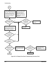
Adjust the Trace Rotation
while watching the CRT display.
Does
the CRT display rotate
with adjustment?
Disconnect the cable to
J82 on the A2 Display
Control board. Measure
the voltage on pin 1
while varying the Trace
Rotation.
Does
the voltage on pin 1
vary from approximately
+5.2V to -5.2V?
No
Yes
Replace the CRT.
Replace the A2 Display
Control board.
Done.
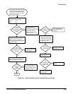
Replace the A2 Display
Control board.
Replace the A2 Display
Control board.
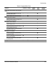
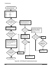
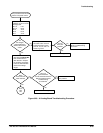
Figure 6Ć28:ăA2 Display Control Board Troubleshooting Procedure