


Circuit Description
Theory of Operation
3Ć6
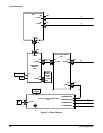
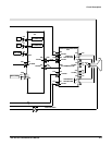
All information (waveforms, text, and cursors) is displayed by the A3 Display
Driver board. It generates the high voltages necessary to drive the CRT. It
also contains the vertical and horizontal amplifier circuitry.
Vertical Output A3
1
The vertical output amplifier provides the final stage of amplification of the
vertical signal. The output of the vertical amplifier is connected to the CRT
vertical plates. Vertical time and frequency compensation networks, some
which are adjustable are also contained in this circuit block. The compensaĆ
tion networks corrects for errors in the time response of the vertical delayĆ
line and variations in time and frequency response of the total vertical sysĆ
tem. The vertical signal at the input of the vertical output stage is sampled
and sent back to the trigger circuitry on the analog board. This feedback
vertical signal is used for calibration.
Horizontal Output A3
2
The horizontal output amplifier provides the final stage of amplification of the
horizontal signal and drives the CRT horizontal plates directly. The input
signal from the analog board is current, and the output signal to the CRT is
a voltage.
High Voltage A3
3
This circuitry provides the necessary static and dynamic levels to support
the CRT biasing and ZĆaxis drive. The ZĆaxis amplifier provides amplification
of the ZĆaxis signal from the analog board which is a current. The output of
the ZĆaxis amplifier is then applied to the DC restorer circuitry which level
shifts this signal to the cathode level. A focus amplifier receives its input
signal from a user control on the front panel. This enables the user to optiĆ
mize the CRT focus. Additional circuitry is provided to support the necessary
bias and operation levels for the CRT.
The External ZĆAxis connector provides the ability to modulate the ZĆaxis
amplifier circuit on the A3 Display Driver board, thus modulating or blanking
the intensity of the CRT display.
Vertical Termination (TAS 485 only)
The processor system sends and receives information to and from the A4
Front Panel board. The Front Panel board reads the frontĆpanel controls and
changes in their settings are reported to the processor system. The frontĆ
panel processor turns the LEDs on and off, generates the probe compensaĆ
tion signal, and processes the probe coding interface signals.
Display Assembly
Front Panel