


Troubleshooting
TAS 455 and TAS 465 Service Manual
6Ć47
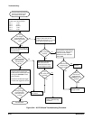
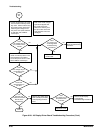
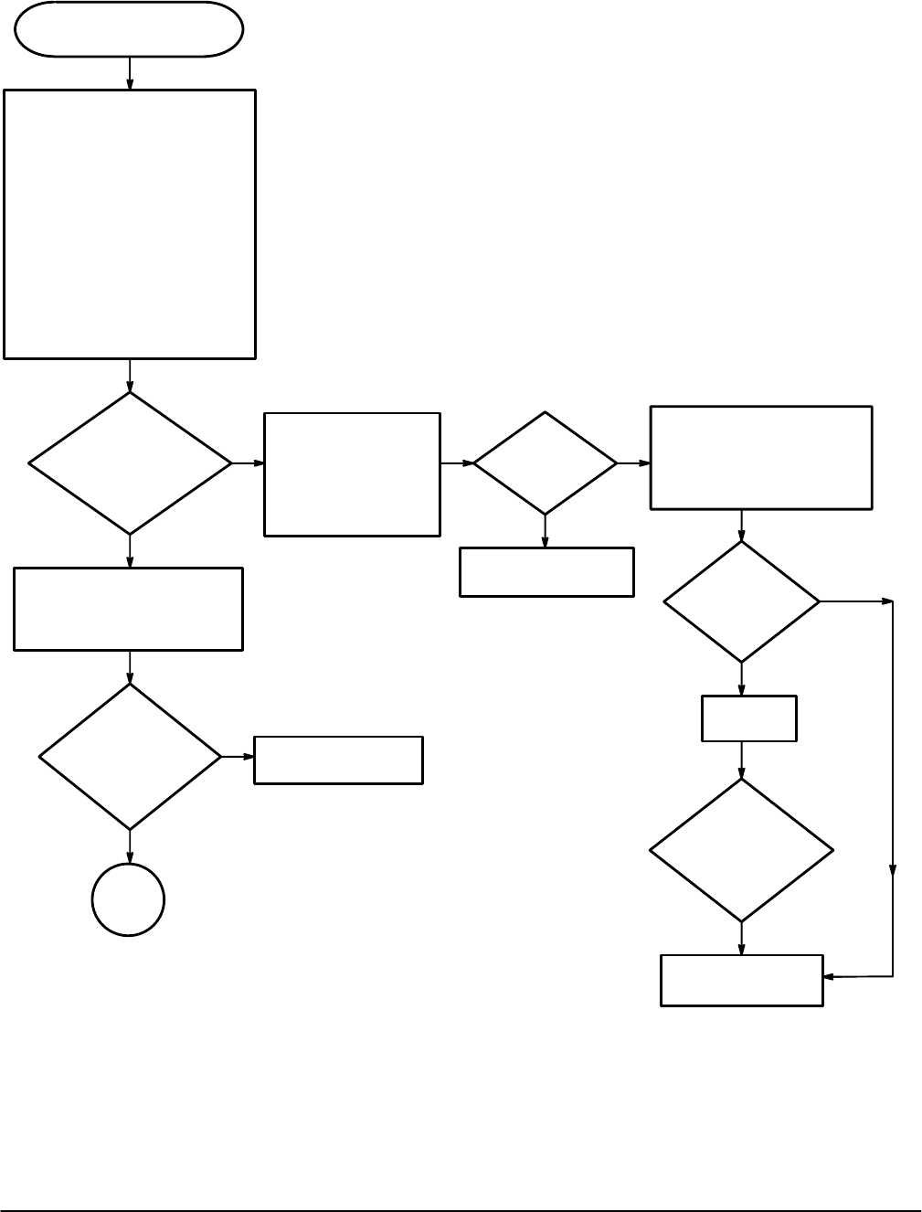
This procedure assumes that
there is front panel control.
Measure the power supply voltages
on the A3 Display Driver board.
W66:
Pin 12 +15V
Pin 10 +8.6V
Pin 9 -8.6V
Pin 6 +5.2V
Pin 1 -5.2V
J70:
Pin 10 +60V
Pin 11 +130V
Pin 13 200V(AC)
Are
the voltages
approximately the
same as the
nominal
value?
No
Yes
Turn the power off.
Disconnect the cables at
W66 and J70 on the A1
Analog board. Check
the pins listed above for
shorts to ground.
Yes
No
Are
any of the pins
shorted?
Replace the A3 Display
Driver board.
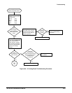
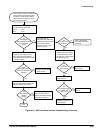
Measure voltage on pin 1 of J71
with a highĆvoltage probe and a
DMM.
Was
the voltage
approximately
-2 kV?
No
Yes
Replace the A63 Power
Supply module.
Go to
Part
Two
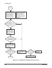
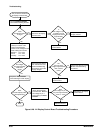
Turn the power off and remove
the power cord. Remove the
fuse from the fuse holder.
Measure the fuse resistance
with a DMM.
No
Yes
Is
the line fuse
resistance less
than 10 W?
Replace the
line fuse.
Replace the A63 Power
Supply module.
Does
the line fuse
blow when the
POWER button is
pressed?
Yes
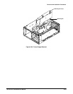
Figure 6Ć26:ăA3 Display Driver Board Troubleshooting Procedure