VIX IM MICROSTEPPER INDEXER DRIVE USER GUIDE
86
Limit Switches
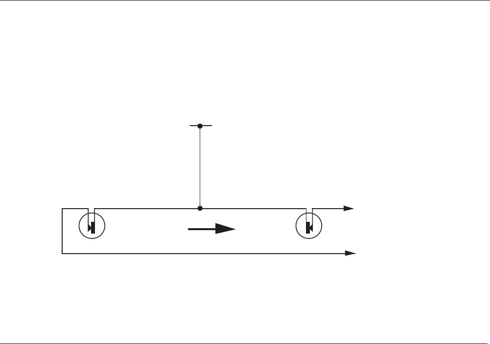
The drive has two limit inputs, the positive limit input and the negative limit input. When
wiring the limit switches it is essential to check that a positive direction command produces
motion towards the positive limit switch. If this is not the case, interchange the motor
connections to A+ and A- to reverse the motor direction.
N
C NEGATIVE
LIMIT
NC POSITIVE
LIMIT
+24V
Positive limit input
Negative limit input
POSITIVE
MOTION
Figure 4-11. Limit and Stop Switch Configuration
If a faulty limit switch, or some other fault caused the indexer to sense both limits becoming
active at the same time all motion would be stopped.


