


3. ELECTRICAL INSTALLATION 33
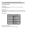
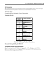
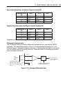
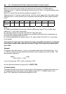
Inputs Depending Upon the State of System Variable EI
Connector Pin
X4
EI=0 EI=1 EI=2
12 STEP+ CW+ A+
7 STEP- CW- A-
13 DIR+ CCW+ B+
8 DIR- CCW- B-
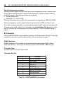
Outputs Depending Upon the State of System Variable EO*
Connector Pin
X4
EO=0 EO=1 EO=2
14 STEP+ CW+ A+
9 STEP- CW- A-
15 DIR+ CCW+ B+
10 DIR- CCW- B-
*Requires encoder feedback input on X2
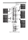
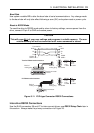
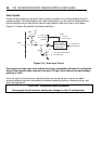
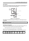
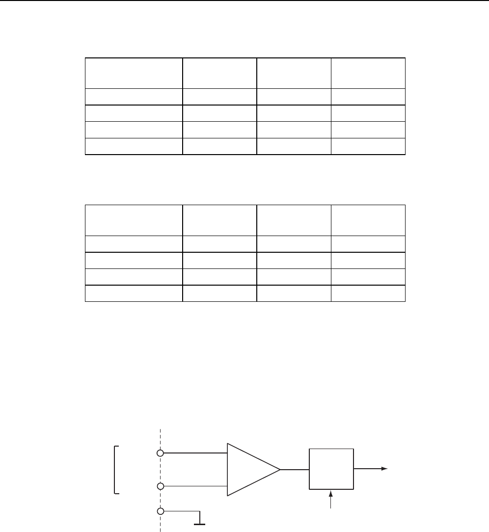
Differential Analogue Input
The ViX stepper drive can accept a differential analogue input for use with the FRATE
command. The input circuit, shown in Figure 3-12, can interface to an external +/-10V
differential signal. Analogue to digital conversion (12-bit resolution) converts the analogue
input to a digital value for use within the drive. Read the value of the analogue input as a
count via system variable AI.
+
-
ANA1-
ANA1+
Input
impedance
200K
Drive
AI, analogue
input expressed
as a count
Software offset controlled
by system variable AO
A to D
Note: both inputs must
be connected - cannot
be used as a single ended
input
0V
GND
Figure 3-12. Analogue Differential Input