


38 VIX IM MICROSTEPPER INDEXER DRIVE USER GUIDE
Bits 0 to 4 control the input resistor pull-down/pull-up of inputs 1 to 5 (SWA setting).
Setting a bit to a ‘1’ sets the input resistor to be a pull-up to +24V, a ‘0’ sets the resistor to be
a pull-down.
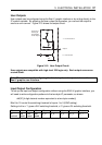
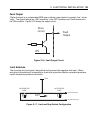
Bits 5 to 7 controls the source/sink operation of outputs 1 to 3.
Setting a bit to a ‘1’ sources current from the +24V rail via the upper half of the output, while
setting a bit to a ‘0’ sinks current from a connected input through the lower output transistor
to 0V.
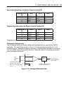
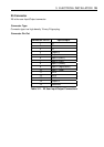
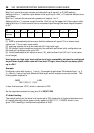
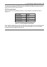
Bit 7 6 5 4 3 2 1 0
IC
content
out_3 out_2 out_1 in_5 in_4 in_3 in_2 in_1
Note:
[1] SWB is automatically set to ensure that the software will report ‘0’ for a closed input
switch and ‘1’ for an open input switch.
[2] sourcing outputs can only be used with 24V high level logic.
[3] 5V tolerant input connections must only be used with pull-down (sink) configuration as
the input pull-up always pulls up to 24V.
[4] Invalid combinations will report an error (*E), and the User Fault (UF) bit 1 is set (value
out of range).
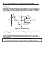
User inputs are high logic level and low level logic compatible, but must be configured
as pull-down inputs when used with low-level 5V logic, since the pull-up always pulls-
up to +24V.
Example
Configure a drive with inputs in_1 and in_2 arranged as pull-down 5V threshold logic. In_3,
In_4 and In_5 as pull-up high threshold level logic, and all outputs as current sources. The
binary pattern required is:
(MSB) (LSB)
00011100 11111100
In hex. this becomes 1CFC, which in decimal is 7420
So the required command to (say) axis 3 is 3W(IC,7420)
IC default setting
The default setting for the drive is all inputs set to 24V threshold, all inputs pulled-down and
all outputs sourcing, which gives a binary pattern of 00011111 11100000, which in hex.
gives 1FE0, resulting in the decimal equivalent of 8160.