


Service Manual Repair procedures 93
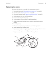
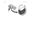
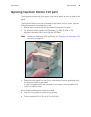
Replacing Expansion Module front panel
The front panel contains the printer buttons. Like the rear panel, the front is sealed to the
Chassis with a rubber O-ring gasket. This gasket can be re-used when replacing the front
panel.
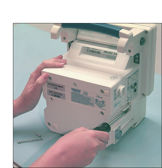
The Expansion Module front panel is attached to the Chassis with four screws. Use the
following procedure to remove the front panel:
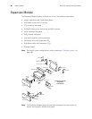
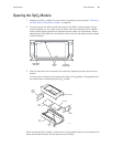
1. Remove the four screws (see the figure below) holding the front panel.
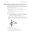
2. For Expansion Module options with Sidestream CO
2
(226, 227, 228, or 229),
disconnect the cables from J1 and J3 on the SSP Board.
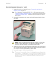
3. Separate the front panel from the Chassis, disconnecting the front panel cable from
the Expansion Module button board.
A rubber O-ring gasket seals the front panel to the Chassis. Save this gasket to re-
install it on the front panel.
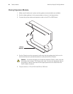
When installing the Expansion Module front panel:
• Verify the O-ring gasket is in place and not pinched.
• Torque screws to 6.65 to 7.35 in-lb (0.75 to 0.83 N-m)
Note
To replace the Sidestream CO
2
assemblies, see “Replacing the Sidestream CO2
assemblies” on page 100.