


98 Repair procedures Welch Allyn Propaq CS Vital Signs Monitor
Replacing the SpO
2
Boards
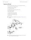
The following instructions describe how to replace the two SpO
2
Boards in the SpO
2
module and in the Expansion Module without a CO
2
option. Instructions for replacing
SpO
2
Boards in an Expansion Module with a CO
2
option are described in “Replacing the
MSP/SpO2 Boards” on page 99.
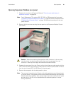
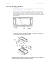
1. Open the SpO
2
Module (“Opening the SpO2 Module” on page 97) or the Expansion
Module (“Expansion Module” on page 90).
2. Disconnect the cable(s) from the SpO
2
SCP Board by carefully releasing the securing
clips and unplugging the connectors.
3. Disconnect the speaker cable from the SCP Board.
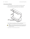
4. Remove the speaker side panel from the chassis.
5. Remove the one or two screws securing the SCP Board and SpO
2
Board to the rear
panel.
6. Lift out the two boards and patient connector side panel as a unit. (The side panel
easily slides out.)
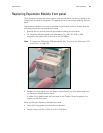
7. Using equal pressure on both sides of the connector, disconnect the patient
connector side panel connector from the SpO
2
Board.
8. Disconnect the two boards by gently pulling them apart.
When installing the SpO
2
Boards first, plug the two boards together. Then:
• Connect the patient connector side panel connector to the SpO
2
Board.
• Set the two boards and side panels in place, making sure that the boards are seated
on the support tabs.
• Torque screws to 4.75 to 5.25 in-lb (0.54 to 0.59 N-m).
• Reconnect the printer and expansion cables to the SCP Board.
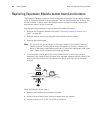
Caution When replacing the SpO
2
Boards, remove both boards with the patient
connector side panel still connected. Attempting to disconnect the patient
connector side panel from the SpO
2
Board before removing both boards with the
side panel can damage the flex-cable between the side panel and the SpO
2
Board.
Caution In the next step, the connector securing clips are fragile and will break
if not handled carefully.