


Service Manual Calibration 47
8. Verify that the input current from the variable dc power supply is less than 1.8 A and
that the green LED on the monitor’s right side panel is on.
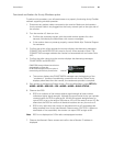
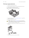
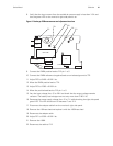
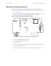
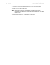
Figure 2. Recharger PCB measurement and adjustment locations
9. Connect the DMM positive lead to P12 pin 1 or 5.
10. Connect the DMM reference (negative) lead to non-isolated ground at TP2.
11. Adjust RP5 to 9.400 ± 0.010 V dc.
12. Move the DMM positive lead to TP4.
13. Adjust RP3 to 2.393 ± 0.015V dc.
14. Move the positive lead back to P12 pin 1 or 5.
15. Vary the input voltage from 12 to 28 V and check that the output voltage remains
constant. The battery load voltage must not vary more than 0.100 V dc.
16. Decrease the power supply voltage from 12 to 7 V while checking the right side panel
green LED. The LED should turn off between 7 and 12 V.
17. Disconnect the adapter cable from the monitor’s right side panel.
18. Remove the 4.9Ω test load and replace it with the 4.65Ω test load.
19. Reconnect the adapter cable.
20. Adjust RP1 to 9.350 ± 0.010 V dc.
21. Remove the 4.65Ω.
22. Reconnect the cable to P12.
CATHODE D33
T3
VLV2
VLV1
VLV3
RP7
NIBP PUMP
P11
P10
P12
+BAT
TP1
P14
TP3
Q1
GND
TP2
OVR SET
TP4
PT2
RP5
RP3
PIN 1
RP1
RP5
TP2
TP4
RP3
RP1
P12