


Service Manual Repair procedures 99
Replacing the MSP/SpO
2
Boards
The following instructions describe how to replace the MSP/SpO
2
Boards in the
Expansion Module with a CO
2
option. Instructions for replacing SpO
2
Boards in SpO
2
module and Expansion Module without a CO
2
option installed are described in “Replacing
the SpO2 Boards” on page 98
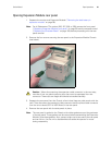
1. Open the Expansion Module (“Expansion Module” on page 90).
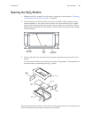
2. Unplug the flex-cable connector J5 from the MSP Board, but do not attempt to
remove the Mainstream CO
2
connector side panel.
3. Disconnect the speaker cable from the MSP Board and remove the speaker side
panel.
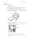
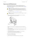
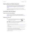
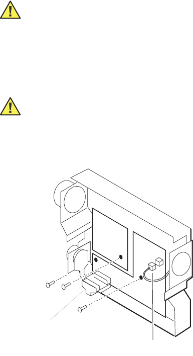
4. Remove the three screws securing the MSP Board and SpO
2
Board to the rear panel
(see the figure above).
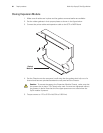
5. Lift out the two circuit boards and SpO
2
patient connector side panel as a unit. (The
side panel easily slides out.)
6. Using equal pressure on both sides of the connector, disconnect the patient
connector side panel connector from the SpO
2
Board.
7. Disconnect the two circuit boards by gently pulling them apart.
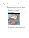
When installing the MSP/SpO
2
Boards:
• plug the two circuit boards together
• connect the patient connector side panel connector to the SpO
2
Board
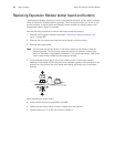
Caution When replacing the MSP/SpO
2
Boards, remove both boards with the
patient connector side panel still connected. Attempting to disconnect the
patient connector side panel from the SpO
2
Board before removing both circuit
boards with the side panel can damage the flex-cable between the side panel and
the SpO
2
Board.
Caution In the next step, the connector securing clips are fragile and will break
if not handled carefully.
Flexible
Connector J5
Speaker
Cable