


Service Manual Functional verification 23
15. Press HOME > SETUP > ALARMS > STAT SET to automatically set heart and
respiration rate alarm limits.
16. Check that the ALARM(S) OFF light is off.
17. Set the patient simulator heart rate to 180 bpm or higher.
18. Check that an alarm violation occurs, causing the tone to sound and the ALARM light
to flash.
19. Software versions 3.6x and greater: Press 4 MIN SUSPND and verify that the tone
turns off and the ALARM light stops flashing.
All other software versions: Press ALARM SUSPEND/RESUME and verify that the
tone turns off and the ALARM light stops flashing.
20. Press HOME to return to the Main Menu.
21. Set the patient simulator heart rate to 80 bpm.
22. Check that the ALARM light is ON.
23. Press SETUP > ALARMS > RESUME.
24. Check that the ALARM light is OFF.
25. Press HOME to return to the Main Menu.
Part 2— Electrical check
Use the same setup for this check described in “Setup” on page 21.
1. Set the patient simulator to provide pacer signals.
2. If the pacer indicator is not on, press ECG/RESP, MORE and select and change the
pacer setting.
3. Check that a dashed vertical line is displayed on the ECG waveform each time a pacer
pulse occurs.
4. Set the oscilloscope to 0.2 second/division sweep and 0.5 Volt/division amplitude.
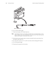
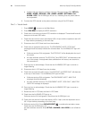
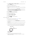
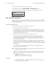
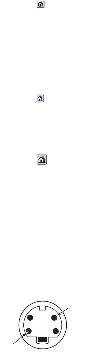
5. Insert a short piece of thin conductive wire into each of the ECG X1000 connector
holes shown in the figure below or use Real Time ECG out cable 008-0320-XX.
6. Connect the scope probe and the scope ground clip to the wires.
7. Check that the scope displays an ECG signal with an amplitude of 1 V ±100 mV
baseline to peak of R-wave.
ECG
(scope probe)
GND
(scope gnd. clip)
0696-69
ECG X1000