


Service Manual Technical overview 113
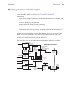
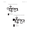
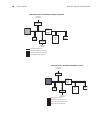
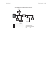
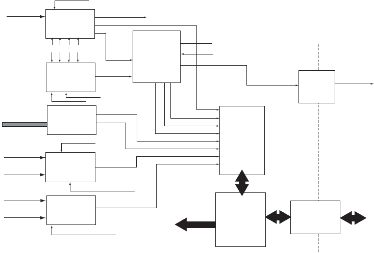
Monitoring electronics system description
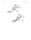
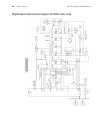
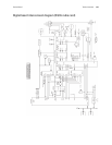
The monitoring electronics reside on the Analog and Digital Boards located in the front
chassis assembly. Refer to the figures page 113, page 114 and page 115.
These circuits:
• acquire the physiological signals from coupling devices (electrodes, transducers, and
probes)
• convert the analog signal to digital data
• process the data for display and alarm monitoring
• display the data and any alarm conditions
• transmits the analog ECG signal across the isolation barrier for real-time analog ECG
output
Isolation barriers on the Analog and Digital Boards isolate the circuits connected to the
patient from circuits connected to other devices including the monitor’s power input.
Communications and power delivery across the isolation barrier are achieved using opto-
couplers and a transformer rated for medical applications.
Microcontrollers (μCs) control patient data processing, alarm monitoring and display.
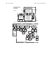
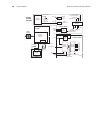
monitoring system diagram
ECG
ACQUISITION
RESP
ACQUISITION
ECG/RESP
BANDPASS
&
OFFSET
COMPENSATION
(ECG: 0.5-40 HZ
OR 0.05-40 HZ)
NIBP
ACQUISITION
IBP
ACQUISITION
TEMPERATURE
ACQUISITION
PATIENT
DATA
MULTIPLEX
DATA
ACQUISITION
PROCESSOR
(DAP)
&
SUPPORTING
CIRCUITS
SYNC OUT/
MARKER IN
TXD/RXD
OPTOCO UPLERS
REAL-TIME
ECG OUT
OPTO-
COUPLERS
5-LEAD
ECG CABLE
CUFF
PRESSURE
TRANSDUCER
CABLES
TEMPERATURE
CABLES
VECG1
VECG2
VRESP
VPRS
VOSC
VINV
VYSI
ACQUISITION
INPUT
CONTROL:
TO ACQUISITION
CIRCUITRY
TEMP CHANNEL SELECT
IBP CHANNEL SELECT
TRANS. PWR.
C LA RA LL
RESP ENBL
RESP_LS
RESP
ECG1 &
ECG2
OFFSET COMPENSATION
DATA (FROM DAP)
RESTORE CONTROL
(FROM DAP)
ECG LEAD SELECT
PACER/ (TO DAP)
VLF (LEAD FAULT)
ISOLATION BARRIER
TO/FROM
DIGITAL
BOARD
TO
ECG OUT
CONNECTOR
MONITORING ELECTRONICS
SYSTEM DIAGRAM