


Service Manual Repair procedures 83
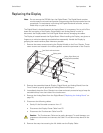
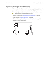
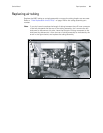
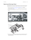
Replacing the Recharger Board
The Recharger Board is secured to the Rear Chassis by four screws. When removing the
Recharger Board, note the location of cables, plumbing, and screws and screw lengths.
1. Remove the battery pack (“Removing the single battery pack” on page 66).
2. Open the monitor (“Opening the monitor” on page 68). (Remove the Rear Chassis
from the Interface Chassis).
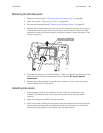
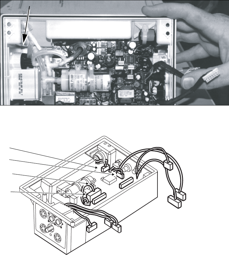
3. Disconnect the air tubing attached to the valves and pump at the junction indicated
below.
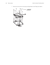
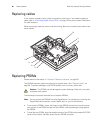
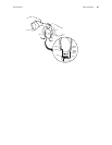
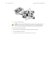
4. Disconnect cables P2, P3, P12, and P15 from the Recharger Board. Note cable routing
for reinstallation.
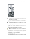
5. Remove the four screws securing the Recharger Board to the Rear Chassis. Note the
screw passing through the pressure transducer is longer than the three that pass
through the Board only.
DISCONNECT PLUMBING AT THIS POINT
P5
P6
P7
P8
P1
P9
P3
P2
P11
P10
P12
P15
P3
P2
P15
P12