


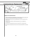

Autotransformer Replacment
Reconnect the autotransformer’s black wire to terminal AC1 at the left-rear corner of the
Motor Control Board.
Connect the blue wire to the lug on the autotransformer.
1. Connect the red wire to the same lug from which it was removed in the previous step. If
there is a question about the available line voltage, or if EL STL messages have been
appearing on the display, check and follow the recommendations in Selecting the
Voltage Tap.
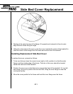
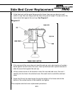
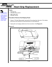
Replace the Shroud
1. Release the should from the bungee cord that has held it to the handrail gooseneck,
and carefully slide the shroud downward so that it rests on the treadmill frame.
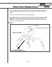
2. Match the screw hole in the lower front edge of the shroud with the mating hole in the
frame, then insert and start the Philips-head screw previously removed.
3. Press down on the sides and front of the shroud to engage the Velcro strips on the
frame.
4. Tighten the screw to complete shroud-replacement procedures.
Test Treadmill Operation
After you have completed replacement of the autotransformer, perform a complete system
test.
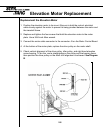
Selecting the Voltage Tap (if there have been EL STL messages).
The treadmill may be operated over a wide range of line voltages. Either of two voltage
taps on the autotransformer may be selected optimize the voltage at the elevation motor. If
the treadmill has been generating EL STL messages on the display, the elevation motor
has either been overheating and shutting down, or it has been failing to respond to the
elevation commands.
Measure the line voltage when the facility’s power line is under a typical load.
• If line voltage is less than 220 VAC, connect the red wire to the lower lug on the
autotransformer.
• If the voltage is greater than 210 VAC, connect the wire to the upper lug.
5.15