


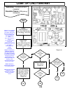
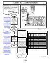
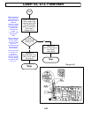
Code: EL STL Flowchart
1A
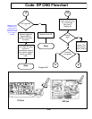
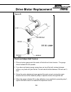
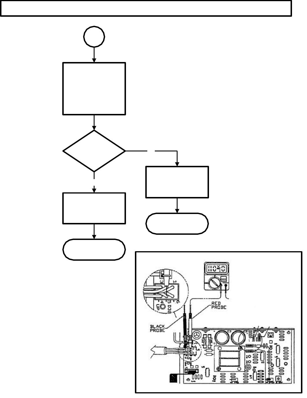
Note 4:
Diagram #2
Place your (red)
meter probe into the
black wire of pin 4,
located at
connector J5. Then
place your (black)
meter probe to AC1
on the M.C.B.
Voltage should
read
+/-110v. or +/-220v
depending on
model.
When pressing the
elevation "DOWN"
key, the voltage
should drop down
to 0v or 1v.
This would indicate
a good response
from the M.C.B.
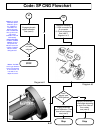
Do the same for pin
5 (red wire), as
shown in
Diagram #4. Then
press the elevation
"UP" key. Voltage
should drop down
to 0v or 1v.
Does
voltage change
at pins 4 & 5
?
Replace the
M.C.B. Then clear all
error codes,
see (note 5)
Replace the
Elevation Motor. Then
clear all error codes,
see (note 3)
NO
Stop
Stop
YES
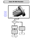
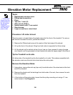
Diagram #2
Using a multi-meter,
verify voltage at the
following pins (4&5)
from the Elevation
Motor connector J5.
See (note 4)
Diagram #2 & 3
4.47