


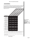
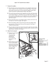
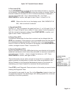

7. Connect the cables.
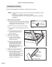
A. Note that there are four threaded holes on the treadmill's front frame
used to fasten the front end panel to the treadmill base. Temporarily
insert button head screws in the two bottom threaded screw holes.
Screw the screws in approximately halfway. See Figure 7.
B. Pick up the front panel and hold it parallel to the floor, with the printed
circuit board facing up. Temporarily mount the panel by placing it over
the two button head screws on the treadmill's front end as referenced in
the previous step. Use the screws to support the panel much like a
shelf. See Figure 7.
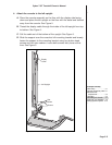
C. Ensure the black mark on the display cable is visible, and wire tie it to
the frame as it exits the upright. See Figure 7.
D. Pinch the retaining clips (to open them) and route the display cable
through each of them across the top of the treadmill. See Figure 7.
Close the retaining clips.
E. Plug all cables into the lower board: (from left to right) the motor/choke
connector, the elevation connector, the display cable connector and the
speed sensor connector. See Figure 7.
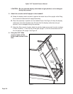
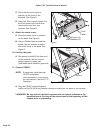
8. Attach the front panel.
A. Remove the front panel
(with the cable
connectors still
attached) off
the two button
head screws. See
Figure 7.
B. While holding the panel
close to the treadmill,
remove the two button
head screws previously
used to support the
front end of the
treadmill base.
Cybex 710T Treadmill Owner’s Manual
Page 5-7
2 Technical Specifications
Specifications . . . . . . . . . . . 2-1
3 Operation
Quick Operation Guide . . . . 3-1
Detailed Operation Guide . . 3-1
Stopping the Treadmill. . . . . 3-3
Control During Operation . . 3-4
Data Readouts. . . . . . . . . . . 3-5
Selecting Programs
& Options . . . . . . . . . . . . . 3-6
Displaying Heart Rate . . . . . 3-6
Use of Programs . . . . . . . . . 3-7
Manual Mode . . . . . . . . . . . 3-8
P1 - Fitness Test Program. . 3-8
P2 - Weight Loss Program 3-10
P3 - Cardiovascular Program 3-12
P4 - Speed Challenge
Program . . . . . . . . . . . . . 3-14
P5 - Express Program. . . . 3-16
P6 - Hill Interval Program . 3-17
P7 - Speed Interval
Program . . . . . . . . . . . . . 3-18
P8 - Pike’s Peak Program . 3-19
P9 - River Run Program . . 3-20
P10 - 5 Kilometer Program 3-21
P11 - Demonstration
Program . . . . . . . . . . . . . 3-22
P101-P110 - Saved
Program . . . . . . . . . . . . . 3-22
Workout Tips. . . . . . . . . . . 3-24
4 Preventive Maintenance
Regular Maintenance
Activities. . . . . . . . . . . . . . 4-1
Cleaning Your Treadmill. . . . 4-1
Running Belt Maintenance . 4-2
Other Preventive
Maintenance . . . . . . . . . . . 4-6
Service Schedule . . . . . . . . . 4-7
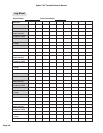
Log Sheet. . . . . . . . . . . . . . . 4-8
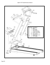
5 Setup & Assembly
Quick Setup . . . . . . . . . . . . 5-1
Choosing & Preparing a Site 5-1
Electrical Power
Requirements. . . . . . . . . . 5-3
Unpacking. . . . . . . . . . . . . . 5-3
Assembling the Treadmill. . . 5-4
Testing the 710T Operation. 5-9
Setting Operation Options. 5-10
6 Customer Service
Contacting Service . . . . . . . 6-1
Serial Number & Voltage . . . 6-1
Warranty . . . . . . . . . . . . . . . 6-1
Return Material Authorization . .
(RMA) . . . . . . . . . . . . . . . . 6-4
Damaged Parts . . . . . . . . . . 6-4
Ordering Parts. . . . . . . . . . . 6-5
7 Service
Service Instruction . . . . . . . . 7-1
Motor Brushes. . . . . . . . . . . 7-1
Motor Current & Voltage . . . 7-4
Running Belt & Deck . . . . . . 7-7
Drive Belt. . . . . . . . . . . . . . . 7-9
Motor
Elevation
Front
Panel
Display
Speed Sensor
Temporarily
Insert
Screws (2)
Retaining
Clips
Figure 7
Tie
Here