


9
620-7920 Rev A
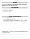
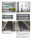
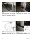
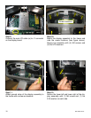
Step 10.
Now install the top display rail. Align the rail’s
mounting holes with the neck holes.
Note: If the electronic display console was assembled
to the rail; remove the screws holding it to the rail and
store the display for later use.
Hint: If one person is assembling the unit, insert two
5/16 screws into top rail holes and use them to align
and temporary hold the rail while you secure it from the
back.
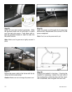
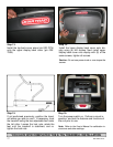
Step 11.
Once the display frame is in place, fasten it to
the neck using the 1/4” Hex key with (2) 5/16-18
x 1.0” socket head screws, (2) 5/16 washers
and (2) lock washers. DO NOT fully tighten yet.
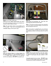
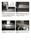
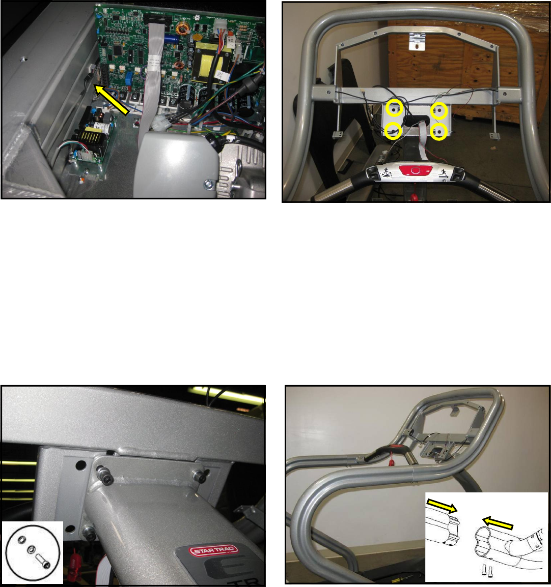
Step 12.
Identify left and right handrails by the part number
affixed on the bottom of rails. (left rail’s part number
is 020-7179, and right rail’s part number is 020-
7181).
Assemble handrail joint as shown. DO NOT fasten
the (2) #10 button head socket screws in the upper
handrail joints until both handrails are in place.
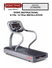
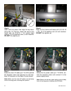
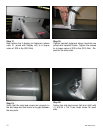
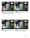
Step 9.
(for E-TRxe model only)
Route the user detect cable behind the eleva-
tion motor and plug it into the user detect con-
nector on the left side of frame.
Note: This user-detect cable is only available on the
E-TRxe model. If your unit is not equipped with an
embedded display; then skip this step.