


23
620-7920 Rev A
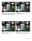
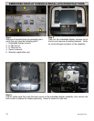
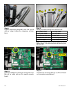
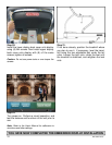
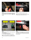
Step 16.
Connect the I/O interface cable (e) to J1 connec-
tor on the translator board located on the top of
the embedded display.
If Equipped, connect the user-detect cable from
the neck to J5 connector on the translator board.
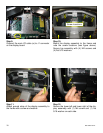
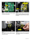
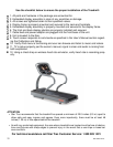
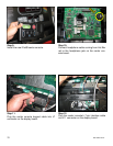
Step 17.
Mount the assembly to the frame and note the
screw locations (see picture above). Secure
top assembly with (4) M4 screws and (4) flat
5/16 washers.
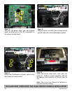
Step 18.
Attach ground strap of the display assembly to
the frame with a screw and washer.
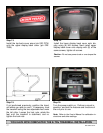
Screw Locations
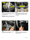
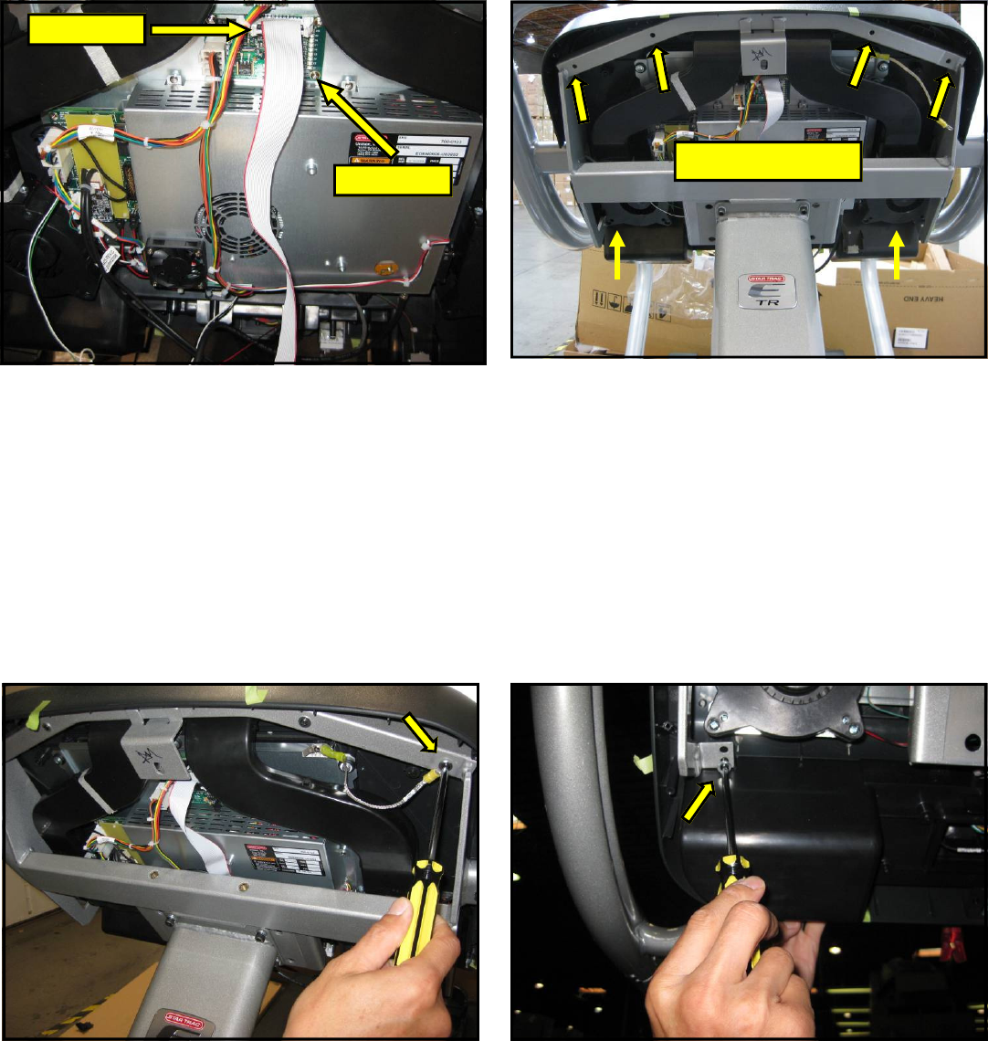
Step 19.
Secure the lower left and lower right of the as-
sembly with (1) M4 screw and (1) flat 5/16
washer on each side.
I/O Interface
User-Detect