


8 MHD56087 - Edition 4
REVIEW COPY 6
-
21
-
02
INSTALLATION
Prior to installing the winch, carefully inspect it for possible
shipping damage. Winches are supplied fully lubricated from the
factory. Check oil levels and adjust as necessary before operating
winch. Refer to “LUBRICATION” section for recommended oils.
• Owners and users are advised to examine specific, local or
other regulations, including American National Standards
Institute and/or OSHA Regulations which may apply to a
particular type of use of this product before installing or
putting winch to use.
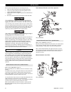
Mounting
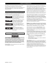
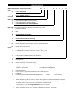
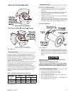
Refer to Dwg. MHP0124 and Table 1 on page 8.
Care must be taken when moving, positioning or mounting the
winch. Ensure that the winch, when lifted, will be properly
balanced. Determine the weight of the winch by referring to the
“SPECIFICATIONS” section. Lift the winch 3 to 4 inches (75 to
100 mm) off the ground. Verify winch is balanced and secure
before continuing lift. Mount the winch so the axis of the drum is
horizontal and that the motor vent cap is not more than 15° off top
vertical center. If the winch is to be mounted in an inverted
position, the motor case must be rotated to position the vent cap at
the top and adequate clearance must be provided for control valve
operation. The breather (8) and drain plug (21) on the disc brake
must be swapped.
• .Winch frame material is not suitable for welding. FA5A
winches must only be mounted by bolting to a suitable
foundation. Do not attempt to mount winch by welding to a
foundation structure. Refer to warning label part number
71270813 on winch.
1. Winch mounting surface must be flat and of sufficient
strength to handle the rated load plus the weight of the winch
and attached equipment. An inadequate foundation may
cause distortion or twisting of winch uprights and side rails
resulting in winch damage.
2. Make sure the mounting surface is flat to within 1/32 inch
(0.8 mm). Shim if necessary.
3. Mounting bolts must be 3/4 inch-NC (18 mm) Grade 8 or
better. Use self-locking nuts or nuts with lockwashers.
4. Tighten 3/4 inch (18 mm) mounting bolts evenly and torque
to 380 ft lbs. (515 Nm) for dry thread fasteners. If the
fasteners are plated, lubricated or a thread locking compound
is used, torque to 280 ft lbs. (380 Nm).
5. Maintain a fleet angle between the lead sheave and winch of
no more than 1-1/2°. The lead sheave must be on a center line
with the drum, and for every inch (25 mm) of drum length, be
at least 1.6 feet (0.5 metre) from the drum. Refer to Dwg.
MHP0498 on page 10.
6. Do not weld to any part of the winch.
(Dwg. MHP0124)
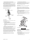
Wire Rope
• Maintain at least 3 tight wraps of wire rope on drum at all
times. Refer to Dwg. MHP0498 on page 10.
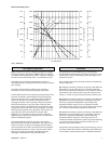
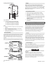
Standard and Open Frame (Face) Winch
Install the winch such that the wire rope, when at the take-off
angle limits does not contact the mounting surface. Refer to Dwg.
MHP1142 on page 9.
•
• Exceeding wire rope take-off angles will cause wire rope to
come into contact with winch frame supports resulting in
damage to wire rope and winch.
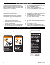
WARNING
Welded mountings
can fail.
Can cause severe
injury or death.
Do not weld, braze or
solder to winch.
71270813
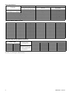
Table 1 - Mounting Bolt Hole Dimensions
Dimension
Drum Length (inches)
12 15 24 27
“A”
in. 17.89 29.89
mm 455 760
“B”
in. 22
mm 559
“C”
in. 0.81
mm 21