


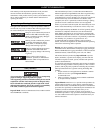

MHD56087 - Edition 4 11
REVIEW COPY 6
-
21
-
02
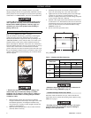
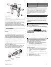
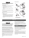
(Dwg. MHP0191)
Air Line Filter
Refer to Dwg. MHP0191 on page 11.
It is recommended that an airline strainer/filter be installed as
close as practical to the motor air inlet port, but before lubricator,
to prevent dirt from entering the valve and motor. The
strainer/filter should provide 20 micron filtration and include a
moisture trap. Clean the strainer/filter periodically to maintain its
operating efficiency.
Air Pressure Regulator
Refer to Dwg. MHP0191 on page 11.
If an air pressure regulator is used, install between the lubricator
and filter.
Moisture in Air Lines
Moisture that reaches the air motor through air supply lines is a
primary factor in determining the length of time between service
overhauls. Moisture traps can help to eliminate moisture. Other
methods, such as an air receiver which collects moisture before it
reaches the motor, or an aftercooler at the compressor that cools
the air to condense and collect moisture prior to distribution
through the supply lines are also helpful.
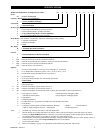
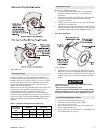
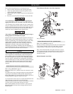
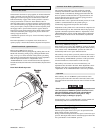
Ball Valve Shut Off
Refer to Dwg. MHP2459 on page 11.
Install in air supply line upstream of control valve. Ensure ball
valve is conveniently located and easily accessible. Advise
operators and support personnel of its location and use.
(Dwg. MHP2459)
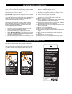
Mufflers (optional feature)
Make sure mufflers are installed in winch exhaust manifold and
control valve exhaust ports. An additional muffler is used on
winches equipped with an emergency stop and overload device.
Check mufflers periodically to ensure they are functioning
correctly.
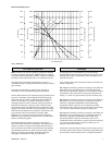
Motor
For optimum performance and maximum durability of parts,
provide an air supply of 700 scfm (20 cu. m/m) at 90 psig (6.3
bar/630 kPa). The air motor should be installed as near as possible
to the compressor or air receiver. Recommended pressures and
volumes are measured at point of entry to air motor directional
control valve.
Emergency Stop and Overload System
Refer to Dwg. MHP2434 on page 50.
Air supply line is connected to air control valve. When emergency
stop or overload valve is activated, all winch movement will stop.
• If winch continues to move (payout load) after emergency
stop activates, brake(s) are not holding load and may require
adjustment or repair.
When control valve senses a preset pressure difference between
ports, a pilot signal is sent to stop flow of air, all winch movement
will stop.
Initial Winch Operating Checks
Winches are tested for proper operation prior to leaving the
factory. Before the winch is placed into service the following
initial operating checks should be performed.
1. When first running the motor inject some light oil into the
inlet connection to provide initial lubrication.
2. When first operating the winch it is recommended that the
motor be driven slowly in both directions for a few minutes.
For winches that have been in storage the following start-up
procedures are required.
1. Give the winch an inspection conforming to the requirements
of “Winches Not in Regular Use” in the “INSPECTION”
section.
2. Pour a small amount of ISO VG 32 (10W) lubricant in the
motor inlet port.
3. Operate the motor for 10 seconds in both directions to flush
out any impurities.
4. Check to ensure oil levels are “full”.
5. The winch is now ready for normal use.
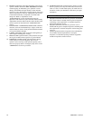
Open
Closed
Ball Valve
Air
Flow
Fitting,
Nipple
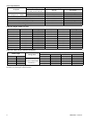
Description of Part Part Number
Fitting, Nipple 51704
Ball Valve 71404628