


MHD56087 - Edition 4 25
REVIEW COPY 6
-
21
-
02
the corroded area. Cut away coating as necessary to expose
corrosion for removal. If the damaged area is less than 1/16
inch (1.6 mm) wide the surrounding thermoplastic coating
can be heated until the material flows together. For surfaces
with damage greater than 1/16 inch (1.6 mm) heat the area
and then apply thermoplastic coating powder (Ingersoll-
Rand Part No. 71308902 [2 oz. (56.7 g)] to fill the area.
Continue heating until coating liquefies and flows together
with the existing coating.
3. Allow the repaired area to cool. Quenching with water is
acceptable. Inspect the repair. Rough spots, minor scorching
and excess coating deposits can be wet sanded to remove the
imperfections. To return the gloss finish, reheat the surface
carefully.
For large bare surfaces or new parts:
1. Coating these components can be done more economically
and with better end results by using an electrostatic powder
application process or flamespray process. Contact Ingersoll
Rand Technical Assistance for more information.
For specific disassembly and assembly information refer to
‘Assembly’ or ‘Disassembly’ in the “MAINTENANCE” section.
Adjustments
Disc Brake
Brake adjustment is not required. If the disc brake does not hold
rated load, disassemble and repair.
NOTICE
• Winches are provided with a breather plug located at the top
of the disc brake housing. If the brake assembly is removed or
repaired ensure the breather is installed and located at the top
of the brake housing during reassembly.
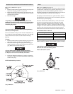
Manual Drum Band Brake (optional feature)
Refer to Dwg. MHP1448 on page 44.
1. Release wire rope tension on the drum.
2. Raise handle (135) to free brake bands (136) and (137).
3. Remove cotter pin (139) and pin (138).
4. Rotate brake link stud (141) clockwise to increase brake
torque.
5. Install pin (138) and check adjustment.
• If brake band cannot be adjusted to hold rated load, replace
brake band assembly.
6. Adjust brake so when brake handle locks (goes over-center),
brake will hold rated load.
7. Install cotter pin (139) and bend ends apart when adjustment
is complete.
For new Brake Linings:
Run-in new brake linings to remove loose material and allow new
lining to conform to brake drum.
1. Operate winch while applying increasing pressure to brake
band handle until drum stops.
• Observe end of load line. Drum should only complete 3-5 full
rotations before stopping.
2. Repeat step 1 twice while operating winch in both directions
(payout and haul-in). The brake link stud may require
tightening to stop drum rotation.
3. Adjust brake as described in steps 1 through 7 above.
Automatic Drum Band Brake (optional feature)
Refer to Dwg. MHP2433 on page 45.
For adjustments described in the following text, references to
“clockwise” and “counterclockwise” directions refer to directions
as viewed from the head end of capscrew (120).
• If brake band cannot be adjusted to hold rated load, replace
the brake band assembly.
1. Loosen jam nut (117) closest to plunger (114).
2. Adjust band assembly using capscrew (120).
a. To loosen band brake, turn capscrew (120) in a
counterclockwise direction.
b. To tighten band brake, turn capscrew (120) in a
clockwise direction.
• If capscrew (120) is not accessible, jam nut (117) [located
closest to the head of capscrew (120)] may be used to adjust
band brake. Ensure capscrew turns with nut.
3. When adjustments are complete tighten jam nut (117) closest
to plunger (114).
Pilot Air Control Valve Adjustment (optional feature)
Refer to Dwg. MHP2416 on page 48.
If winch operating speeds differ from performance specifications
pilot air control valve may require adjustment.
1. Loosen nut (264) and adjust adjusting screw (270), located in
valve cap end (268), until drum speed for no-load haul-in
equals drum speed for full load payout.
2. Rotate screw (270) ‘out’ to increase drum speed and ‘in’ to
decrease drum speed. It is suggested that a chalk mark be
placed on drum flange so that drum rpm can be accurately
counted.
Constant Tension Manifold (optional feature)
Refer to Dwg. MHP2416 on page 48.
The regulator is preset at 0 psig (0 bar/0 kPa), therefore requires
adjustment when winch is installed. To adjust for specific load
applications, regulator pressure may be adjusted to increase or
decrease tension setting.
Regulator gauge and regulator are accessible through cover.
• When adjusting regulator, ensure winch control lever is
locked in neutral position and tension selector lever is in the
NORMAL position.
• Winch supply air is NOT turned off during regulator
adjustments. To prevent accidental winch operation, allow
only a single person, trained in operation, safety and
maintenance of this product, to conduct regulator
adjustments.