


MHD56087 - Edition 4 15
REVIEW COPY 6
-
21
-
02
Winch Brakes
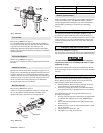
Automatic Disc Brake
The automatic disc brake is spring applied, air released. When the
winch is operated in payout direction, air pressure acting on the
diaphragm overcomes spring pressure and releases brake. The
brake automatically engages when winch operation is returned
from payout direction to neutral or when shifted to haul-in
direction. When winch is in neutral or haul-in positions the brake
air is vented and brake springs apply the brake. The springs, acting
on the pressure plate, compress brake friction and separator plates
and engage brake to prevent drum rotation in payout direction.
The cam type sprag clutch assembly allows drum rotation in haul-
in direction with brake plates engaged, but prevents drum from
rotating in payout direction.
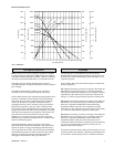
A minimum air pressure of 25 psi (1.72 bar/172.4 kPa) is required
to release brake.
Disc brake adjustment is not required. If disc brake does not
operate properly it must be disassembled, inspected and repaired.
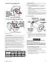
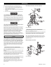
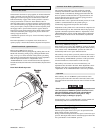
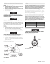
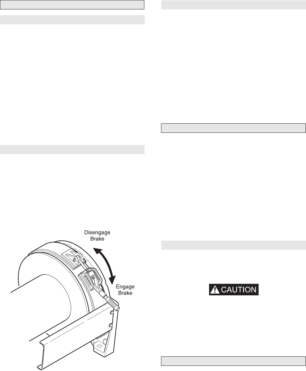
Manual Drum Brake (optional feature)
Refer to Dwg. MHP1375 on page 15.
The manual drum brake may be applied by pushing down on the
handle and released by pulling up. By pushing the handle down
fully, it will go over-center and lock in that position, preventing
drum rotation. The drum brake must be kept properly adjusted to
hold the required load. Refer to ‘Adjustments’ in the
“MAINTENANCE” section. If brake band cannot be adjusted to
hold the rated load, the brake must be disassembled, inspected and
repaired.
Drum Brake Handle Operation
(Dwg. MHP1375)
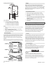
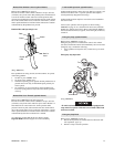
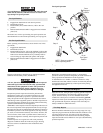
Automatic Drum Brake (optional feature)
The automatic drum brake is a spring applied, air released,
externally mounted brake which uses an air actuated, spring
loaded cylinder to automatically disengage the brake when the
motor is operated in either the haul-in or payout directions. Air
pressure directed to the cylinder overcomes spring pressure to
release brake and allow drum to rotate.
When the control valve is placed in the neutral position, air in the
cylinder is vented which allows the cylinder spring to
automatically engage brake and prevent drum rotation.
Adjustments to the cylinder clevis can be made to compensate for
normal brake lining wear. The drum brake must be kept properly
adjusted to hold the required load. Refer to ‘Adjustments’ in the
“MAINTENANCE” section. If brake band cannot be adjusted to
hold rated load, the brake must be disassembled, inspected and
repaired.
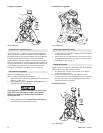
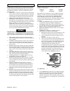
Constant Tension Manifold (optional feature)
Refer to Dwg. MHP2436 on page 52.
With auxiliary valve (744) in the ‘NORMAL’ position, the winch
control valve will provide normal winch operation. With auxiliary
valve selector in the ‘TENSIONING’ position, the winch will
automatically haul-in wire rope to maintain tension.
The auxiliary valve provides a preset air pressure to the air motor
and disc brake. This allows the brake to be released, and winch to
over haul during ‘TENSIONING’ operations. In this position the
winch will maintain a constant tension on the wire rope.
The auxiliary valve comes set at zero from the factory. All
adjustments must be made in the field. These adjustments can be
changed at any time to accommodate the current load. Refer to
‘Adjustments’ in the “MAINTENANCE” section for procedures.
Operation
Place auxiliary valve in ‘NORMAL’ position and use winch
control to position the end of load line at the load. Connect load
line to the load and use winch control to remove all slack from the
load line.
• Ensure slack load line is taken up by operating winch control
valve with selector in NORMAL position. If selector lever is
placed in TENSION position the winch will immediately
attempt to establish line tension causing line to ‘snap’
resulting in injury or damage to property.
Actuate auxiliary valve to ‘TENSIONING’ position. Winch will
automatically haul-in to maintain tension on load line.
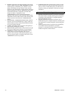
Free Spool (optional feature)
Refer to Dwg. MHP2414 on page 61.
The Free Spool option allows wire rope to be spooled from the
drum without operating winch motor.
During normal winch operations the free spool is in non-free spool
position. The output shaft connects outboard upright to drum. The
free spool handle is in the ‘DOWN’ position.