


MHD56087 - Edition 4 27
REVIEW COPY 6
-
21
-
02
3. Disconnect and tag air lines.
4. To drain oil refer to “LUBRICATION” section.
5. Remove capscrews and nuts securing winch to its foundation
and move to a suitable work area before beginning
disassembly.
WARNING
• The air motor weighs approximately 260 lbs. (118 kg).
Adequately support air motor before removing motor
mounting capscrews.
6. Remove the ten capscrews (197), lockwashers (196),
securing the motor assembly to the motor adapter (71).
Using a hoist to support the motor, pull the motor straight
away from the winch. Refer to the ‘Motor Disassembly’
section if motor disassembly is required.
7. Remove drive shaft (61) and coupling (60).
8. If equipped, disconnect drum band brake as described below.
Manual Drum Brake:
Refer to Dwg. MHP1448 on page 44.
a. Remove cotter pin (144) and pin (138).
b. To disassemble further, refer to ‘Manual Band Brake
Disassembly’ on page 29.
Automatic Drum Brake:
Refer to Dwg. MHP2433 on page 45.
a. Remove capscrews (101), spacers (102) and (103).
b. Remove and save spacer (105).
c. Loosen two nuts (117).
d. Remove capscrew (120), pivot bar (119) and nuts (117).
e. To disassemble further, refer to ‘Automatic Band Brake
Disassembly’ on page 29.
9. Remove drum guard and any other externally mounted winch
attachments. Refer to applicable sections for disassembly
instructions.
CAUTION
• There are a total of eight capscrews securing the brake cover
to the brake housing. Two of these capscrews (41) hold the
brake assembly together, but do not attach to the outboard
upright. One capscrew attaching the brake assembly is located
directly beneath the brake air line fitting connection; the other
is located 180 degrees from the air fitting. The heads of these
two capscrews sit deeper into the counterbores of the brake
cover. Do not remove these two capscrews (41) until the brake
has been separated as an assembly from the winch and the
directions in the ‘Disc Brake Disassembly’ section have been
reviewed.
10. Disconnect and remove brake hose (75). Remove six
capscrews (1) attaching disc brake assembly to outboard
upright (26). Remove disc brake assembly by tapping around
housing with a soft hammer or mallet while pulling out and
away from upright in a horizontal direction. Remove dowel
pin (20) and store until reinstallation. To further disassemble
the disc brake assembly, refer to Dwg. MHP1230 on page 42
and the ‘Disc Brake Disassembly’ section.
11. Using a hoist to support the drum, remove side rails (65), one
at a time, by removing four capscrews (66) attaching each
side rail to uprights (26) and (68).
12. Remove the inboard (motor end) upright (68) by pulling
straight away from drum (62) in a horizontal direction.
Remove oil seal (29) and bearing (30) from upright. Discard
oil seal. Discard bearing if inspection indicate replacement.
13. Remove capscrews (33) and cover (72) from drum if not
equipped with a band brake.
14. Outboard upright (26) removal:
a. For units without disc brake: remove cover (2) by
removing six capscrews (1). Pry cover and gasket (18)
from upright. Pull upright away from drum (62) in a
straight horizontal direction. Remove output shaft (28),
oil seal (29) and bearing (30) from upright. Discard oil
seal. Discard bearing if inspection indicates
replacement. Note the condition of capscrews (27)
located in output shaft. Note positions for reinstallation.
b. For units with a disc brake: pull upright away from
drum (62) in a straight horizontal direction. Remove
output shaft (28), oil seal (29) and bearing (30) from
upright. Discard oil seal. Discard bearing if inspection
indicates replacement.
• Ensure the reduction gear oil is drained before disassembly
and that the drain and fill plugs are removed. When using
jacking bolts, ensure the cover lifts evenly by turning bolt one
full turn and then repeating on the other bolt. If cover jams,
remove jacking bolts and gently tap around the cover to reseat
it before starting over. Careful prying of the cover along its
diameter during jacking, using a soft material wedge, to guide
the cover is acceptable. Care must be taken not to scar, gouge
or damage the machined finishes on the cover and the reducer
housing mating surfaces during parts separation.
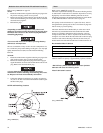
15. Stand drum on end with reduction gear on top. Remove
reduction gear assembly from drum (62) by removing six
capscrews (33) attaching end cover (34) to drum. Screw two
7/16 - 20 UNF x 1-1/2 inch capscrews into the threaded holes
in cover (34). Turn both screws evenly until cover is
separated from housing. Remove cover.
16. Screw two 1/2 - 13 UNC x 1-1/2 inch capscrews into the
threaded holes in the reducer housing (48). Turn both screws
evenly until housing is separated from drum. Attach suitable
lifting eyes to the capscrews and remove housing from drum.
17. To further disassemble reduction gear refer to ‘Reduction
Gear Disassembly’ section.
K5C2-X Control Valve Disassembly
Refer to Dwg. MHP2427 on page 46.
Handle Removal
If handle is not damaged it is not necessary to disassemble
completely.
1. Carefully pry off plug (935).
2. Remove capscrew (901) and tab lock washer (909).
• Observe spring (937) connection during disassembly. This
spring is under tension and is required to return handle to
neutral position.
3. Carefully pull handle assembly (930) from reverse valve
(943). Remove spring (937).