


MHD56087 - Edition 4 13
REVIEW COPY 6
-
21
-
02
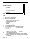
Remote Pilot Pendant Control (optional feature)
Refer to Dwg. MHP2233 on page 13.
Provides for remote winch control at distances of up to 50* feet
(15 metres) away from winch. The pendant pilot control throttle is
a two lever movable control station for winch operation. Pilot
pressure from pendant pilot control throttle activates winch control
valve. The winch control valve, located on winch motor, controls
motor speed and direction of drum rotation. Direction of rotation
is determined by the pendant lever pressed.
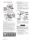
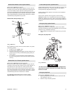
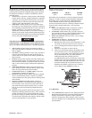
Pendant Hose and Operating Levers
(Dwg. MHP2233)
Press pendant levers using smooth, even movements. To operate
winch using pendant:
1. To haul-in, press ‘RIGHT’ lever.
2. To payout, press ‘LEFT’ lever.
3. To throttle operating speed, regulate amount pendant lever is
pressed. Press lever fully for maximum speed; partially for
slower speeds.
4. To stop haul-in or payout operation, release pendant lever.
Lever will spring return to off position and winch operation
will stop.
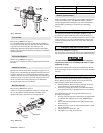
Remote Pilot Lever Throttle (optional feature)
Refer to Dwg. MHP2444, item 358 on page 58.
Provides for remote winch control at distances of up to 50* feet
(15 metres) away from winch. The lever pilot control throttle is a
fixed mount lever control station for winch operation. Pilot
pressure from lever pilot control throttle activates winch control
valve. The winch control valve, located on winch motor, controls
motor speed and direction of drum rotation. Direction of rotation
is determined by direction in which lever is shifted.
* For distances greater than 50 feet (15 metres) contact
Ingersoll-Rand Technical Support for control suitability.
Underwound Operation (optional feature)
Underwound operation is where wire rope haul-in or payout is off
the bottom of drum. This is a special operation and requires a
winch specifically designed for this usage.
Underwound operation requires a reverse bias valve installed in
the control valve.
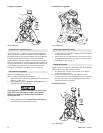
Control valve operation will be opposite as shown in Dwg.
MHP1809 on page 12. As viewed from air motor end, lift slider
handle up to unlock control lever. Move control throttle handle to
the left (counterclockwise) to payout, and to the right (clockwise)
to haul-in.
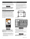
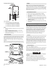
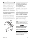
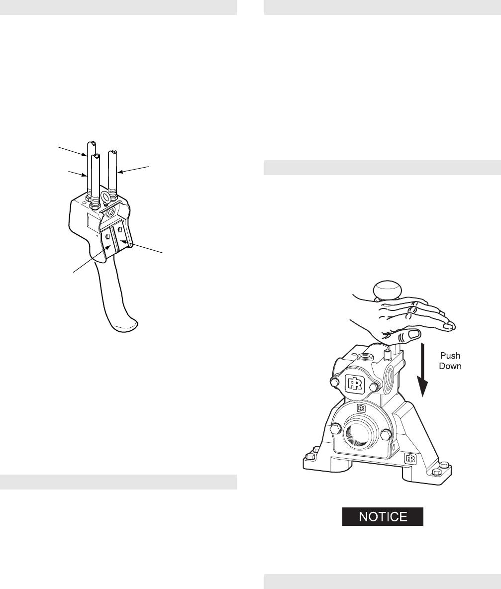
Emergency Stop (optional feature)
Refer to Dwg. MHP2047 on page 13.
Emergency stop device is located on the control valve. When
activated, winch drum rotation will immediately cease. To activate
emergency stop, conduct the following:
1. Press (push down) red palm valve, located on top of control
valve.
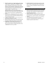
Emergency Stop Operation
(Dwg. MHP2047)
• If winch overload occurs, overload device, if equipped, also
stops winch. To operate winch after an overload, reduce load
and reset overload.
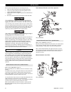
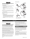
Emergency Stop Reset
Refer to Dwg. MHP2048 on page 14.
1. Rotate red stop button, in counterclockwise direction until
red stop button ‘pops’ up.
2. Winch is ready to resume operation.
Payout
Load
Haul-In
Load
Red
Green
Yellow