


MHD56087 - Edition 4 7
REVIEW COPY 6
-
21
-
02
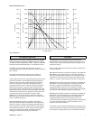
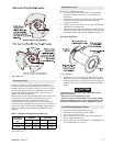
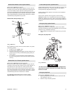
FA5A Performance Curve
(Dwg. MHP0895)
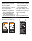
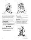
Description of Operation
FA5A winches are air powered, planetary geared units designed
for lifting and pulling applications. FA5A winches are supplied
with either an internal automatic disc brake, a manual or automatic
externally mounted drum band brake, or a combination of both.
The output from an externally mounted piston air motor is
transmitted through a coupling and shaft to the planetary reduction
gear assembly.
The output from the planetary reduction gear assembly is
connected to the wire rope drum through the output shaft.
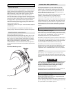
The disc brake attaches to the outboard upright opposite the motor
end and is connected to the intermediate sun gear through the
brake shaft. The disc brake is automatically applied when the
winch is in the neutral or operated in the haul-in positions;
disengaged when the winch is operated in the payout direction.
During winch operation a sprag type clutch in the disc brake
allows drum rotation in the haul-in direction with the disc brake
engaged. This ensures the brake will respond quickly to hold the
load when winch operation stops. Operation of the winch in the
payout direction directs pressurized air to the disc brake
diaphragm to overcome spring tension and release the brake.
When the payout operation is complete the air is vented and the
brake is automatically applied.
The drum band brake operates by applying a friction force
between the drum band and the winch drum. The manual brake
requires an operator to engage and disengage the brake using a
lever located near the air motor end of the winch. The automatic
drum band brake operation is similar to the disc brake with the
following exception: the automatic drum band brake fully
disengages in both the haul-in and payout directions.
Traceability
Load bearing parts are documented to provide traceability.
Documentation includes chemical and physical properties of raw
material, heat treating, and hardening, tensile and charpy tests as
required for the part.
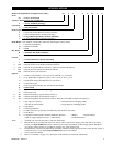
Units with M1, M2 or M3 in the model code have traceable load-
bearing components.
M1–Material Traceability certificates according to EN 10204 (Ex
DIN 50049) 2.2 on load bearing parts. Conformity documents
affirm (by the manufacturer) that parts are in compliance with the
requirements of the order based on non-specific inspection and
testing (i.e. results are typical material properties for these parts).
M2–Material Traceability certificates according to EN 10204 (Ex
DIN 50049) 3.1b on load bearing parts. Conformity documents
affirm (by a department independent of the manufacturing
department) that the actual parts are in compliance with the
requirements of the order based on specific inspection and testing
(i.e. results are actual material properties for these parts).
M3–Material Traceability certificates according to EN 10204 (Ex
DIN 50049) 3.1b on load bearing parts. Conformity documents
affirm (by a department independent of the manufacturing
department) that the actual parts used in the product are in
compliance with the order based on specific inspection and testing
(i.e. results are actual material properties for these parts in a
finished, as delivered condition).
Components with part numbers ending in CH are charpy parts for
use under extreme cold conditions. Traceability requirements must
be stated when reordering these parts for continued certification.
2000
6000
4000
8000
10000
12000
14000
16000
1st Wrap Line Pull
1st Wrap
Half Drum
Full Drum
0
300
500
400
600
700
800
900
200
100
8.5
14.2
11.3
16.9
19.8
22.7
25.5
5.7
2.8
907
2122
1814
3629
4536
5443
6350
7257
0
0
16
32
48
64
80
96
112
128
144
160
176
192
208
224
240 256
Line Pull (lbs x 100)
Line Pull (kgs)
Line Speed (ft/min)
Air Consumption (scfm)
Air Consumption (m /min)
3
Half Drum
Full Drum