


28 MHD56087 - Edition 4
REVIEW COPY 6
-
21
-
02
Reverse Valve Removal
1. Remove capscrews (938), (925) and washers (924) from seal
bracket (939). Remove seal bracket from housing. Remove
and discard ‘O’ rings (941) and (942).
2. Remove capscrews (901) and washers (902) from exhaust
flange (955). Remove flange from housing. Remove and
discard ‘O’ ring (942).
3. Move reverse valve (943) out exhaust flange side of housing
until ball (916) is visible on reverse valve. Allow ball (916) to
drop out of bushing (944) and remove ball (916).
4. Remove bushing (944) out exhaust flange side of housing.
• Dowel pin (945) allows the bushing to be removed only from
the exhaust flange side of housing. Ball (916) retains reverse
valve (943) in bushing (944).
• Do not remove reverse valve (943), bushing (944) and ball
(916) at the same time, damage may occur to bushing.
• Take care to not allow ball (916) to drop in motor. If this
occurs it may be necessary to disassemble motor to retrieve
ball (916).
Piston Removal
1. Remove capscrews (901) and washers (902) from piston
cover (919). Remove cover and discard gasket (918).
2. Remove capscrews (901) and washers (902) from poppet
cover (903). Remove cover and discard gasket (904).
3. Remove the following items from housing poppet bore:
spring (905), poppet cap (906) and poppet seal (907).
4. From poppet side, push piston (922) out of housing. Remove
‘O’ rings (921) and (923) and discard.
Pilot Valve Removal
• For easier removal it is recommended to use I-R pilot seat
tool (920). This must be purchased separately. Operation of
this tool (920) is similar to an allen wrench or screw driver.
If pilot valve is not damaged it is not necessary to disassemble
completely.
1. Remove plug (912).
2. Remove pilot valve assembly (910) as an assembly.
3. Discard and replace pilot valve assembly (910) if necessary.
K5C2-EX Control Valve Disassembly
Refer to Dwg. MHP2434 on page 50.
Handle Removal
Follow disassembly instructions for K5C2-X Control Valve.
Reverse Valve Removal
1. Remove capscrews (938), (925) and washers (924) from seal
bracket (939). Remove seal bracket from housing. Remove
and discard ‘O’ rings (941) and (942).
2. Remove capscrews (721) and washers (902) from exhaust
flange (955) and exhaust adapter (723). Remove and discard
‘O’ rings (942) and (722).
3. Move reverse valve (943) out exhaust flange side of housing
until ball (916) is visible on reverse valve. Allow ball (916) to
drop out of bushing (944) and remove ball (916).
4. Remove bushing (944) out exhaust flange side of housing.
• Dowel pin (945) allows the bushing to be removed only from
the exhaust flange side of housing. Ball (916) retains reverse
valve (943) in bushing (944).
• Do not remove reverse valve (943), bushing (944) and ball
(916) at the same time, damage may occur to bushing.
Piston Removal
Follow disassembly instructions for K5C2-X Control Valve.
Pilot Valve Removal
Follow disassembly instructions for K5C2-X Control Valve.
Emergency Stop Removal
1. Remove adapter (706) and E-Stop button (705).
2. Remove plunger (707). Remove and discard ‘O’ rings (703).
3. Pull spring (711) out of valve housing and discard.
Overload Valve Removal
1. Remove cap (700). Remove and discard grommet (701).
2. Pull out plunger (702), remove and discard ‘O’ rings (703).
3. Remove capscrews (901) and washers (902) from cover (719)
underneath valve housing.
• Cover (719) retains spring (718). To remove capscrews (901)
and washer (902) unscrew in a crisscross pattern.
4. Remove adjusting screw (720).
5. Remove and discard ‘O’ ring (716), gasket (714) and ‘O’ ring
(713) from piston.
6. Do not remove seal from piston, if piston appears damaged or
worn replace.
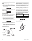
Motor Disassembly
Refer to Dwg. MHP0690 on page 40.
1. Remove the five capscrews (255) from the exhaust flange
(254).
2. Remove the rotary valve housing (247) by pulling it out of
the motor housing (217) as an assembly with the exhaust
flange (254).
3. Remove rotary valve (250) by pulling it out from the
assembly through the motor end of the rotary valve housing
(247).
4. Remove exhaust flange (254) from rotary valve housing
(247) by gently tapping edges of flange with a soft hammer
until seal is loosened.
5. Remove each cylinder head (201) by removing the four
capscrews (200). Remove head gaskets (209) and discard.
6. Remove mounting flange (216) from motor by pulling
straight away from motor.
7. Pull the cylinder liner (208) straight out.
8. Position the piston (204) at the top of its stroke. In this
position, with the cylinder liner pulled out in step 7, the wrist