


MHD56087 - Edition 4 33
REVIEW COPY 6
-
21
-
02
• Cover (719) retains springs (718), adjustment nut (717) and
plate (715). Insert capscrews (902) and washers (901) in a
crisscross patter until tightened evenly.
8. Insert adjusting screw (720), refer to ‘OPERATION’ section
for overload valve adjustment.
Freespool Assembly
Refer to Dwg. MHP2414 on page 61.
1. Assemble shaft support (503) to output shaft (28) and secure
with socket capscrews (504). Torque capscrews to 18 ft lb (25
Nm).
2. Apply Loctite
® 609 to handle (512) and press into free spool
shifter (515).
3. Apply Loctite
® 242 to threads of plunger (511) and screw
into detent plate (514).
4. Place new ‘O’ ring (501) into groove in housing (502).
Lubricate with a mixture of half ISO VG 68 (SAE 20W)
lubricant and half molybdenum disulfide lubricant
compound.
5. Lubricate free spool shifter assembly (507) with above
compound, place into housing (502).
6. Slide shaft support (503) and output shaft (28) as an assembly
into housing (502) until groove in shaft support aligns with
pin (516) in free spool shifter assembly (507). Tap into place
with suitable soft headed hammer.
7. Insert this assembly into winch drum (62), twisting slightly to
align gears and until housing (502) fits tightly against
outboard upright (26). Align marks made in ‘Disassembly’
step 2.
8. Install capscrews (505) into housing (502) tighten and torque
to 18 ft lb (25 Nm).
9. Apply light coat of EP grease to face of housing (502), place
gasket (18) on housing face and align bolt holes.
10. Using capscrews (1) and washers (902) install cover (2) onto
housing (502).
11. Operate free spool several times to ensure smooth operation.
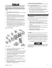
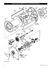
Reduction Gear Assembly
Refer to Dwg. MHP0649 on page 38.
1. Install oil seal (58) in housing (48).
2. Install needle bearing (46) if removed during disassembly.
3. Install thrust washers (44) on input sun gear (43).
4. Install input sun gear assembly (43) in housing (48).
5. Install (40) on either side of input gear carrier (42).
6. Install input gear carrier (42) on input sun gear (43).
7. Align intermediate sun gear (39) with input gear carrier (42)
and install in gear carrier (42). Take care not to damage teeth
on either part while installing.
8. Install thrust washer (35) and output gear carrier (36) in
housing (48). Align with intermediate sun gear (39). Take
care not to damage teeth on either part while installing.
9. Align holes in cover (34) with housing (48) and secure with
capscrews (33). Torque to 60 ft lbs (81 Nm).
10. With drum standing on end, place reduction gear assembly
into drum. Place Loctite
® 515 on mating surfaces of housing
(87) and end cover. Align the 3/8 inch NPT holes in the end
cover with counterbore marks on the housing mating flange.
Secure in place by evenly installing sixteen capscrews (33).
Torque capscrews to 60 ft lbs. (81 Nm).
11. Cover the reduction gear to prevent dirt and contaminants
from entering assembly and place in a safe place until ready
for assembly to winch uprights.
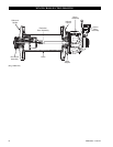
Winch Assembly
Refer to Dwg. MHP0649 on page 38.
NOTICE
• Unless otherwise stated capscrew torque values listed are for
lubricated or plated threads. This assembly uses “blue bolts”
in numerous locations. These are plated and should not be
lubricated.
1. Using a hoist, support the drum.
2. Install bearing (30) in inboard (motor end) upright (68). With
oil seal (29) lip facing towards drum, install oil seal in
inboard upright.
3. Install output shaft (28), bearing (30) and oil seal (29) in
outboard upright (26). Install the outboard upright onto drum
by aligning splines of output shaft to reduction gear output
carrier assembly splines.
a. a. For units with disc brake, refer to the ‘Disc Brake
Assembly’ section.
b. b. For units without disc brake, ensure three capscrews
(27) are installed in the output shaft. Apply Loctite
® 515
on mating surfaces of outboard upright (26) and end
cover (2). Install gasket (18). Install six capscrews (1)
and secure end cover to upright. Torque capscrews to 18
ft lbs (24 Nm).
4. If unit is equipped with drum band brake, install the drum
band brake bracket and piston assemblies. Do not attach the
brake band assembly (147) or (130). Refer to the applicable
‘Drum Band Brake’ section for instructions.
5. Install coupling (60) on shaft (61) and install on end of the
input sun gear (43), located in the reduction gear assembly.
6. If unit is equipped with drum band brake, place brake band
assembly (147) or (130) onto drum brake flange. Place
inboard (motor end) upright (68) on drum.
7. Loosely attach the side rails (65) to the uprights (26) and (68)
using four capscrews (66) for each sideframe. Tighten
capscrews and torque to 75 ft lbs (102 Nm) for dry threads, or
55 ft lbs (75 Nm) if thread lubrication is used.
8. Align holes in motor adapter (71) and install on upright.
Secure with six capscrews (73). Torque capscrews to 125 ft
lbs (170 Nm) for dry threads, or 95 ft lbs (129 Nm) if thread
lubrication is used.
9. If equipped with drum band brake, attach band brake
assembly (147) or (130). Refer to applicable assembly
sections.
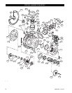
Manual Drum Band Brake Assembly
Optional feature. Refer to Dwg. MHP1448 on page 44.
1. Press bushings (143) into brake band pivot brackets. Bushing
flanges must be to motor upright side.
2. Attach adapter plate (145) to motor side upright (68) loosely
with capscrews (132) (apply Loctite
® 242 to threads) and
washers (131).
3. Place brake band (136) and (137) onto drum and rotate
around drum (close to mounting position). Spread brake
band halves (136) and (137) apart slightly and slide in over
drum flange. Place brake band pivot bracket over pin in
adapter plate (145).
4. Repeat this procedure for other brake band halves (136) and
(137).