


30 MHD56087 - Edition 4
REVIEW COPY 6
-
21
-
02
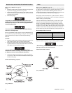
3. Rotate brake link stud (141) counterclockwise until free
from brake handle.
4. Remove grip from brake handle (135). Loosen screws in
brake handle until handle can be freed from brake band
bracket, remove brake handle. Remove pivot nut (134).
5. Remove cotter pin (144) and washer (142).
6. Loosen capscrews (132).
7. Spread brake band (136) and (137) apart slightly and slide
out over drum flange. Rotate brake band around drum and
remove.
8. Repeat this procedure for other half of brake band (136) and
(137).
9. Remove capscrews (132), washers (131), and adapter plate
(145).
10. Press bushings (143) out of brake band pivot brackets.
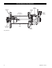
Free Spool Disassembly
Refer to Dwg. MHP2414 on page 61.
1. Relieve pressure in the air lines and winch air components by
operating the winch control several times after the air supply
has been turned off.
WARNING
• Shut off, bleed down and disconnect the air supply line
before performing any disassembly procedures.
• Do not attempt repairs with load on wire rope.
2. To assist in reassembly, place match marks on the housing
(502) and outboard upright (26).
3. Remove free spool shifter assembly (507) by pulling it out of
housing (502). This assembly is held in place by ‘O’ ring
(501). Remove and discard ‘O’ ring (501).
4. Pin (508) and handle (512) are held in position by Loctite
®
applied during assembly. To remove these parts, carefully
heat the shifter (515) until parts are removable.
5. Remove capscrew and washers (902). Remove cover (2) and
gasket (18). Discard gasket.
6. Remove capscrews (505) and carefully pull housing (502)
away from outboard upright (26).
7. Remove output shaft (28) from drum (62).
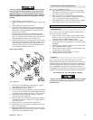
Reduction Gear Disassembly
• It is not recommended to disassemble reduction gear.
Refer to Dwg. MHP0649 on page 38.
1. Place the reduction gear assembly on a clean work bench
such that reducer housing (48) with oil seal (58) is down.
2. Remove capscrews (33) and cover (34) from housing (38).
3. Remove thrust washer (35) and output carrier assembly (36).
4. Remove the input carrier assembly (42) by grasping the
intermediate sun gear (39) and removing as an assembly. This
also removes the input sun gear (43). Ensure that thrust
bearing (45) and thrust washers (44), located on the end of
the input sun gear (43), are removed.
NOTICE
• Do not disassemble carrier assemblies (36) and (42). Replace
if damaged or worn.
5. Remove the oil seal (58) and discard. Remove the caged
needle bearing (46) only if replacing. To remove press
bearing out of housing.
Cleaning, Inspection and Repair
Clean all winch component parts in solvent (except the drum
brake bands and disc brake friction plates). The use of a stiff
bristle brush will facilitate the removal of accumulated dirt and
sediments on the housings, frame and drum. If bushings have been
removed it may be necessary to carefully scrape old Loctite
® from
the bushing bores. Dry each part using low pressure, filtered
compressed air. Clean the drum brake band using a wire brush or
emery cloth. Do not wash the drum brake band in solvent. If the
drum brake band lining is oil soaked, it must be replaced.
Inspection
All disassembled parts should be inspected to determine their
fitness for continued use. Pay particular attention to the following:
1. Inspect all gears for worn, cracked, or broken teeth.
2. Inspect all bushings for wear, scoring, or galling.
3. Inspect shafts for ridges caused by wear. If ridges caused by
wear are apparent on shafts, replace the shaft.
4. Inspect all threaded items and replace those having damaged
threads.
5. Inspect the drum band brake lining for oil, grease and
glazing. If the drum band brake lining is oil-soaked,
excessively greasy or overly glazed replace the brake band.
Remove small glazed areas of band brake lining by sanding
lightly with a fine grit emery cloth.
6. Measure the thickness of the drum band brake lining. If the
drum brake band lining is less than 0.062 in. (2 mm) thick
anywhere along the edges replace the brake band assembly
for automatic (104) and manual (136) and (137).
Repair
Actual repairs are limited to the removal of small burrs and other
minor surface imperfections from gears, shafts, housings and
machined surfaces. Use a fine stone or emery cloth for this work.
1. Worn or damaged parts must be replaced. Refer to the
applicable parts listing for specific replacement parts
information.
2. Inspect all remaining parts for evidence of damage. Replace
or repair any part which is in questionable condition. The
cost of the part is often minor in comparison with the cost of
redoing the job.
3. Smooth out all nicks, burrs, or galled spots on shafts, bores,
pins, or bushings.
4. Examine all gear teeth carefully, and remove nicks or burrs.
5. Polish the edges of all shaft shoulders to remove small nicks
which may have been caused during handling.
6. Remove all nicks and burrs caused by lockwashers.
Assembly
General Instructions
• Use all new gaskets and seals.
• Replace worn parts.
• Assemble parts using match marks applied during
disassembly. Compare replacement parts with originals
to identify installation alignments.
• Lubricate all internal parts with rust and oxidation
inhibiting lubricant, ISO VG 100 (SAE 30W).