


10 MHD56087 - Edition 4
REVIEW COPY 6
-
21
-
02
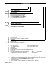
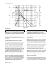
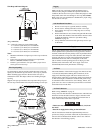
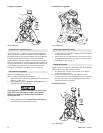
Wire Rope and Drum Diagram
(Dwg. MHP0498)
‘A’ = 1.6 feet (0.5 metre) per inch of drum length:
‘A’ = 19.2 feet (5.85 metres) for 12 inch drum.
‘A’ = 24.0 feet (7.31 metres) for 15 inch drum.
‘A’ = 38.4 feet (11.7 metres) for 24 inch drum.
‘A’ = 43.2 feet (13.2 metres) for 27 inch drum.
Notes:
1. Maintain a minimum of 3 tight wraps of wire rope on drum at
all times.
2. Ensure wire rope does not exceed top layer requirement.
Refer to “SPECIFICATIONS” section.
3. If drum is grooved ensure wire rope width is proper size to
seat in grooves on last wrap.
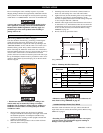
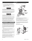
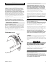
Wire Rope Spooling
To compensate for uneven spooling and the decrease in line pull
capacity as the drum fills up, use as short a wire rope as practical.
When rewinding apply tension to the end of the wire rope to
eliminate line slack. This helps achieve level winding and tight
spooling.
Support wire rope spool and have wire rope come off top of spool
and over top of winch drum. This will prevent damage to wire rope.
(Dwg. MHP2450)
Rigging
Make sure all wire rope blocks, tackle and fasteners have a
sufficient safety margin to handle the required load under all
conditions. Do not allow wire rope to contact sharp edges or make
sharp bends which will cause damage to wire rope, use a sheave.
Refer to the wire rope manufacturer’s handbook for proper sizing,
use and care of wire rope.
Safe Installation Procedures
1. Do not use wire rope as a ground (earth) for welding.
2. Do not attach a welding electrode to winch or wire rope.
3. Never run the wire rope over a sharp edge. Use a correctly
sized sheave.
4. When a lead sheave is used, it must be aligned with the center
of the drum. The diameter of the lead sheave must be at least
18 times the diameter of the wire rope. Refer to Dwg.
MHP0498 on page 10.
5. Always maintain at least three full, tight wraps of wire rope
on the drum.
Air Supply
The air supply must be clean, free from moisture and lubricated to
ensure optimum motor performance. Foreign particles, moisture
and lack of lubrication are the primary causes of premature motor
wear and breakdown. Using an air filter, lubricator and moisture
separator will improve overall winch performance and reduce
unscheduled down time. The air consumption is 700 scfm
(20 cu. m/min) at rated operating pressure of 90 psig (6.3 bar/
630 kPa) at the winch motor inlet. If air supply varies from
recommended, then winch performance will change.
Air Lines
The inside diameter of the winch air supply lines must be at least
1-1/2 inch (38 mm). Before making final connections, all air
supply lines should be purged with clean, moisture free air or
nitrogen before connecting to winch inlet. Supply lines should be
as short and straight as installation conditions will permit. Long
air transmission lines and excessive use of fittings, elbows, tees,
globe valves etc. cause a reduction in pressure due to restrictions
and surface friction in the lines.
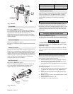
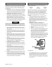
Air Line Lubricator
Refer to Dwg. MHP0191 on page 11.
Always use an air line lubricator with these motors. The lubricator
must have an inlet and outlet at least as large as the inlet on the
motor directional control valve. Install the air line lubricator as
close to the air inlet on the motor as possible.
• Lubricator must be located no more than 10 ft. (3 m) from
the motor.
• Shut off air supply before filling air line lubricator.
The air line lubricator should be replenished daily and set to
provide 6 to 9 drops per minute of ISO VG 32 (SAE 10W) oil. A
fine mist will be exhausted from throttle control valve when air
line lubricator is functioning properly.
CORRECT
Wire Rope
Spooling
Wire Rope
Spooling
Wire Rope
Spooling
Spool
INCORRECT
Winch
Drum
Spool
Winch
Drum
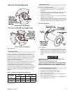
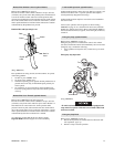
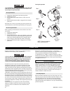
CORRECT
Underwound
Overwound
Spool
Winch
Drum