


MHD56087 - Edition 4 29
REVIEW COPY 6
-
21
-
02
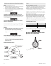
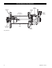
pin (203) can be removed. Remove one retainer ring (205)
from either side of piston (204). Push the wrist pin (203) out
by hand from one side. If the wrist pin is too tight it is
acceptable to carefully heat the piston to 200° F (93° C) or
less and then push the wrist pin out.
• If original piston, wrist pin, connecting rod or cylinder liner
are to be reassembled, number each set. Also add radial
alignment marks for each piston and cylinder liner to the
motor housing.
9. Remove the remaining cylinder liners and pistons as
described in steps 7 and 8. To remove the crank assembly, all
pistons and cylinder liners must be removed.
10. Crank assembly (231) can now be removed with the oil
slinger (230) by pulling straight out from the motor housing
(217). Use care while guiding the connecting rods (206)
through the inside of the motor housing.
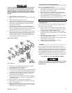
Crankshaft Disassembly
1. Remove cotter pin (236) and the pin nut (237).
2. Remove lock pin (235) by carefully driving it out of its
location. Use care not to damage the threads.
3. Pull the crankshaft valve end (231) off the crankshaft.
4. Remove connecting rod rings (234), connecting rod bushing
(233), sleeve (232) and connecting rods (206). Record the
five connecting rod (206) numbers and foot directions so they
can be reinstalled in the same order.
5. Oil slinger (230) does not have to be removed unless
damaged. If removal is required, heating of the five screws
(229) may be necessary to loosen the Loctite
® connection.
Disc Brake Disassembly
Refer to Dwg. MHP1230 on page 42.
NOTICE
• Prior to disassembly, matchmark the cover (2), housing (6)
and support plate (19) to assist in proper alignment of parts
during reassembly.
1. Remove capscrew (1) securing brake to upright (26).
2. Remove brake shaft (25) and retainer ring (23). Place brake
assembly on a flat surface with cover (2) on top. Remove
elbow fitting (80) and brake valve (79). Alternately and
evenly loosen the two capscrews (41) until the brake spring
(17) compression has been relaxed. Remove capscrews.
3. Remove cover (2) and diaphragm (3).
4. Using a small tipped screwdriver or similar tool, remove ring
(4). Remove diaphragm support (5).
5. Remove housing (6) by lifting straight away from brake parts.
Collect the three dowel pins (9) and store until reinstallation.
Inspect pins for deformation, wear and damage. Replace if
parts fail inspection.
6. Alternately remove the six separator plates (14) and five
friction plates (13).
7. Remove the pressure plate (15) and springs (17).
8. Grasp the outer race (12) and remove the sprag clutch as an
assembly. Remove the spacer (11) between the sprag clutch
assembly and support plate (19).
9. Remove gasket (18) from support plate (19). Discard gasket.
10. To remove the bearing (21) from the support plate (19) first
remove the retainer ring (22) and then press the bearing out
of the support plate recess.
NOTICE
• To prevent accidental damage, remove the bearing (21) only
if it requires replacement.
11. Separate the sprag clutch assembly into its component parts.
The sprag clutch assembly consists of the inner race (10), two
spacers (11), the outer race (12) and the sprag clutch (16).
The sprag clutch can be further disassembled into two
wearing plates and the sprag cage.
Automatic Drum Band Brake Disassembly
Optional feature. Refer to Dwg. MHP2433 on page 45.
1. Loosen jam nut (117) closest to plunger (114). Turn capscrew
(120) counterclockwise until disconnected from plunger.
2. Disconnect air line (76) from exhaust valve (79). Remove
exhaust valve from brake cylinder (121). With the aid of a
strap wrench, remove brake cylinder (121) and components
as an assembly by turning brake cylinder counterclockwise
until disconnected from brake bracket (106).
3. Disconnect brake bracket (106) from band assembly by
removing three capscrews (101), spacers (102) and spacer
tubes (103). Remove spacer plate (105).
4. Disconnect brake bracket from motor end upright (68) by
removing two capscrews (107) and two capscrews (112).
•
• Springs (124) and (127) exert a considerable force on cover
(125). Extreme care must be taken when disassembling the
cylinder assembly and removing cover (125).
5. To disassemble cylinder (121) assembly into its component
parts conduct the following:
a. Use a press to compress cover (125) enough to remove
retainer ring (126). Slowly, and carefully, relax the load
exerted on cover (125) by springs (124) and (127).
Remove cover and springs.
b. Remove washer (128).
c. Remove piston (123) assembly.
d. Disassemble piston assembly into component parts by
removing retainer ring (141) and separating cylinder rod
(108) from piston (123). Remove ‘O’ rings (109), (110)
and (122). Discard ‘O’ rings.
6. Remove plunger (114) assembly and spring (113) from brake
bracket (106).
Manual Drum Band Brake Disassembly
Optional feature. Refer to Dwg. MHP1448 on page 44.
The winch does not have to be removed or disassembled to
disassemble the manual band brake.
• Release wire rope tension on the drum and disconnect main
air supply line.
1. Raise handle (135) to free brake bands (136) and (137).
2. Remove cotter pin (139) and pin (138).