


34 MHD56087 - Edition 4
REVIEW COPY 6
-
21
-
02
5. Place washer (142) over pin in adapter plate (145) and secure
with cotter pin (144). Bend cotter pin ends apart.
6. Insert pivot nut (134) into brake handle (135).
7. Place brake handle (135) into bracket in brake band halves
(136) and (137) and tighten screws in handle. Slide grip over
brake handle.
8. Place brake link stud (141) into pivot nut (134) and rotate
clockwise until approximately 1 inch (25 mm) of threads are
exposed.
• Refer to ‘Adjustment’ section for instructions on adjusting
brake.
9. Lift up brake handle (135) until hole in brake link stud (141)
and bracket in brake band halves (136) and (137) are aligned.
Insert pin (138) and secure with cotter pin (139). Bend cotter
pin ends apart.
10. Push brake handle (135) down to the lock position.
11. Torque capscrews (132) to 50 ft lbs (68 Nm).
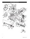
Automatic Drum Band Brake Assembly
Optional feature. Refer to Dwg. MHP2433 on page 45.
For ease of assembly install bracket (106), cylinder (121)
assembly and brake handle stop to motor end upright (68) prior to
assembling upright to drum.
1. Assemble brake cylinder (121) as follows:
a. Install ‘O’ ring (122) on piston (123).
b. Heavily coat piston and cylinder rod with “LubriPlate”
MO-LITH No. 2 or equivalent lubricant. Install ‘O’
rings (109) and (110) on cylinder rod (108). Place
cylinder rod (108) into piston (123) and secure in place
using retainer ring (111).
c. Install piston assembly in brake cylinder (121).
d. Install washer (128) and springs (124) and (127).
•
• Springs (124) and (127) exert a considerable force on cover
(125) when assembled. Extreme care must be taken when
assembling and installing cover (125) and retainer ring (126).
e. Using a press, slowly compress cover (125) and springs
until retainer ring groove is accessible. Install retainer
ring (126). To ensure that retainer ring is properly
installed, tap end of retainer ring with a punch until
entire retainer ring rotates in brake cylinder groove.
Slowly release press and ensure retainer ring securely
holds cover in place.
2. If not accomplished during ‘Winch Assembly’ steps, install
bracket (106) to inside of motor end upright (68) and secure
in place using capscrews (107) and (112). Torque capscrews
to 35 ft lbs (48 Nm).
3. Assemble roller (116) in plunger (114) and secure using
dowel pin (115). Heavily coat plunger assembly with
“LubriPlate” MO-LITH No. 2 or equivalent lubricant. Install
spring (113) and plunger assembly in brake bracket (106).
Align groove in plunger towards hole in motor end (68)
upright.
4. Align cylinder rod roller surface to groove in plunger. Turn
cylinder (121) clockwise until snug. Adjust cylinder (121)
such that air hose connection port is horizontal and towards
the motor.
Conduct the following when winch is assembled, but prior to
mounting to foundation. The motor end of winch should be raised
enough to allow access to brake components located on the inside
surface of inboard (motor end) upright (68).
5. Place spacer (105) between upper brake band flange and
bracket. Attach band assembly (104) to bracket (106) using
three capscrews (101), spacers (102) and spacer tubes (103).
Torque capscrews to 35 ft lbs (48 Nm).
6. Install pivot bar (119) and capscrew (120) through lower
flange of brake band assembly (104). At lowest point of
threads, place a bead of Loctite
® 680 and install jam nut
(117) fully. Jam nut threads must become coated with
sealant. Install second jam nut (117) to approximate middle
of thread length. Thread capscrew (120) into bottom of
plunger (114) a minimum of five thread lengths. Lock in
place, against plunger, using jam nut (117). Adjust brake as
described in ‘Drum Band Brake Adjustment’ section.
Adjusting Automatic Drum Band Brake
Optional feature. Refer to Dwg. MHP2433 on page 45.
• This adjustment is done after a rebuild. It is only a rough
adjustment intended to remove major slack prior to adjusting
with a load.
This procedure can be done at a work bench using a 50 psig
(3.44 bar/344 kPa) air supply applied to the brake cylinder. After
completion of this procedure the brake must further be adjusted
using the recommended air supply and a test load.
1. Insert a length of 3/8 inch NC threaded rod, fully into the
cylinder rod (108). With brake band slack and no air
supplied to brake, push end of threaded rod to position
plunger all the way inside brake bracket (106). Place a nut on
threaded rod, and locate nut until it is just touching cover
(126). Apply air to brake. Threaded rod should move out
from cylinder approximately 1 inch (25 mm).
2. Tighten capscrew (120) in plunger (114) to remove slack
from band brake. Release air pressure. Nut should move
closer to end cover (125) and stop.
3. Repeat step 1 until nut stops at approximately 9/16 inch
(14 mm) from cover (125).
4. Refer to further adjusting in ‘Automatic Drum Brake
Adjustment’.
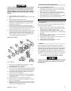
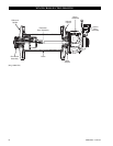
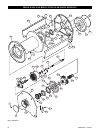
Disc Brake Assembly
Refer to Dwg. MHP1230 on page 42.
1. Install bearing (21) into support plate (19) and secure with
retainer ring (22).
2. In this order, place spacer (11), sprag clutch (16), outer race
(12) and spacer (11) on inner race (10). Test sprag clutch
operation. Refer to Dwg. MHP1197 on page 35.
NOTICE
• Correct sprag clutch installation prevents clockwise rotation
(brake engages) and allows counterclockwise rotation when
viewed from the cover (2) end of the brake assembly.