


22 MHD56087 - Edition 4
REVIEW COPY 6
-
21
-
02
Reduction Gear and Disc Brake Fill and Drain Procedures
Refer to Dwg. MHP0501 on page 22.
To Fill:
1. Rotate the winch drum to align the reduction gear plugs to the
fill position. Fill plug position is at top center.
2. Remove the fill plug on the reduction gear and the level plug
on the disc brake housing. Fill slowly until oil flows from the
disc brake level plug hole.
3. Reinstall the plugs.
NOTICE
• Depending on ambient temperature it may take several
minutes for oil to flow from the disc brake level plug hole. Wait
10 minutes after oil starts to flow from level plug hole before
reinstalling plug fittings.
CAUTION
• Do not over fill. Excess oil will reduce operating efficiency
and increase oil temperature.
The use of unsuitable oil may result in excessive temperature rise,
loss of efficiency and possible damage to the gears. Use only high
quality Extreme Pressure (EP) rust and oxidation inhibiting
lubricant.
To Drain:
1. Rotate the winch drum to align the reduction gear plugs to the
drain position. Drain plug is located at bottom center.
2. Remove the reduction gear drain plug and install long pipe
nipple threaded at one end to 3/8-18 NPT. Remove drain vent
plug. Remove the disc brake drain plug.
NOTICE
• Always drain oil into a suitable container and inspect
drained oil for evidence of damage, metal shavings, dirt, water,
etc. Dispose of oil in an environmentally safe manner.
3. Collect the drained oil and dispose of properly. If replacing
oil, refer to ‘To Fill’ instructions. Reinstall the reduction gear
and disc brake plugs.
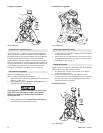
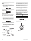
Oil Fill and Drain Plug Locations
(Dwg. MHP0501)
Motor
Refer to Dwg. MHP2126 on page 22.
The motor is splash lubricated by oil in the motor housing and has
no other means of lubrication. It is therefore important to use only
high quality rust and oxidation inhibiting lubricant to ensure
maximum performance and minimum downtime for repairs. Refer
to ‘Recommended Motor Lubricant’ table on page 22.
Oil capacity for the winch motor is 3 quarts (2.8 litres). Add oil
through the filler opening until oil flows from the level plug hole.
Add oil slowly to prevent spilling.
The motor should be level-checked daily or at the start of each
shift after any accumulated water has been drained off. When
motors are operated in temperatures below freezing, wait long
enough at end of shift for water to separate from oil but not long
enough for it to freeze. Drain the water then refill to the level plug
located on side of motor housing. If desired, all the oil may be
drained at the end of the shift and the motor refilled with new oil.
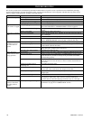
Recommended Motor Lubricant
* Units are shipped from factory with ISO VG 68 (SAE 20W)
lubricant. Motor oil capacity is approximately 3 quarts (2.8 litres).
• DO NOT use synthetic lubrication in air motor. Synthetic
lubricants will cause oil to blow by piston.
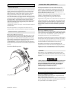
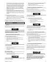
Motor Lubrication Locations
(Dwg. MHP2126)
Temperature Recommended Viscosity
Under 32° F (0° C) ISO VG 46 (SAE 10W)
32° to 80° F (0° to 27° C) ISO VG 68 (SAE 20W) *
Above 80° F (27° C) ISO VG 100 (SAE 30W)