


MHD56087 - Edition 4 31
REVIEW COPY 6
-
21
-
02
Thermoplastic Coated Parts Assembly
CAUTION
• During application of thermoplastic coating to assemblies
use a flame to localize the heat. Do not heat entire assembly.
Assemblies contain gaskets, ‘O’ rings and other components
that may be damaged by exposure to excessive heat.
1. When assembling parts already coated, the mating areas can
be heated to soften the coating enough to flow together and
seal the parts.
2. When installing a new component in an assembly, remove
coating from existing parts as necessary to ensure parts mate
correctly.
3. Install fasteners and torque as required. Apply coating to bare
areas as described in ‘Thermoplastic Coating’ repairing
surfaces instructions in the “MAINTENANCE” section for
areas larger than 1/16 inch (1.6 mm).
4. Allow the repaired area to cool. Quenching with water is
acceptable. Rough spots, minor scorching and excess coating
deposits can be wet sanded to remove the imperfections. To
return the gloss finish, reheat the surface carefully.
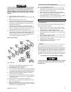
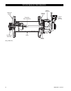
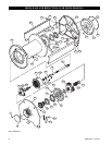
Motor Assembly
Refer to Dwg. MHP0690 on page 40.
1. Install two seal rings (251) on each end of rotary valve (250).
Place bearing (252) onto the rear of rotary valve (250) and
press into position. Press only on the bearing inner race. With
the rotary valve housing (247) exhaust flange side down,
install rotary valve into housing.
2. Install ‘O’ ring (244) into motor housing (217).
3. Install the rotary valve housing gasket (243) onto rotary valve
housing (247). With the exhaust flange down on the bench,
install motor housing (217) onto rotary valve housing (247).
Check for any evidence of damage to ‘O’ ring (244) when the
rotary valve housing is fully engaged. Install exhaust flange
(254) and tighten capscrews (255) to 50 ft lbs (68 Nm).
4. If removed, press crank bearing (228) on crank assembly
(231). Press only on the inner race of the bearing.
5. Place crank assembly (231) on a work bench with the oil
slinger (230) down and slide the sleeve (232), with tang up,
on the crankpin.
6. Slide connecting rod bushing (233) over the sleeve (232) and
first connecting rod ring (234) with the chamfer up.
7. Install the connecting rods (206) in the same order as
removed, with all feet pointing in the same direction, using
the first connecting rod ring (234) to hold one side of the
connecting rod feet.
8. Slide the second connecting rod ring (234) over the other side
of the connecting rod feet with the chamfer on the ring facing
down (toward the stem of the connecting rod).
9. Slide the crank shaft valve end over the crank pin while
simultaneously aligning the tang on the sleeve (232) with the
slot in the crank shaft.
10. Rotate and position the crank shaft valve end relative to the
crank pin to allow installation of the lock pin (235).
11. Tap the lock pin (235) into place and install the pin nut (237).
Torque nut to 60 ft lbs (81 Nm).
12. Install cotter pin (236).
13. Install roll pin (240) and bearing (228) into the valve end of
the crank shaft.
14. Check that all connecting rods move freely around the crank.
Position the crank assembly (231) into the motor housing
(217). Ensure the bearing (228) is seated and connecting rods
(206) are centered in the cylinder holes.
NOTICE
• Make certain that the roll pin (240) and the three lugs on the
rotary valve (250) line up with the corresponding hole and lugs
on the crank shaft.
• Do not allow the rotary valve (250) to slide back in rotary
valve housing (247). If the rotary valve slides in too far, the
rotary valve and crankshaft will not align properly and will
restrict further assembly.
15. Rotate the crank assembly until one connecting rod (206) is
at the top of its stroke. Install a piston (204) with its rings
(202 and 207) to the connecting rod (206) with wrist pin
(203) and retainer rings (205).
16. Install a new cylinder head gasket (209) before installing the
cylinder liner (208).
17. Install the cylinder liner (208) over the piston (204) by
compressing both piston rings (202) and (207) with a single
band ring compressor.
18. Install cylinder head (201) over the cylinder and secure
cylinder head to motor housing (217) with four capscrews
(200). Torque capscrews to 60 ft lbs (81 Nm).
19. Repeat Steps 15 through 18 with the remaining cylinders.
NOTICE
• When installing the two lowest cylinder heads (201), use seal
washers on capscrews (200).
20. Rotate motor by hand. Motor should rotate without binding.
21. Install mounting flange (216) and gasket (226) on the front of
the motor housing (217). Make sure notches on both parts are
aligned.
22. Lightly lubricate ‘O’ ring (70) and install in groove on motor
adapter (71).
23. Install eye bolts (213), vent cap assembly (210) and pipe plug
(218) in the motor housing (217). From the rotary valve
housing end of the motor, ensure plug (218) is installed in the
left oil fill hole of the motor.
24. Install motor on winch at motor adapter (71) using capscrews
(197), lockwashers (196) and washers (198).
25. Ensure oil drain (225) and level plug (225) are installed.
K5C2-X Control Valve Assembly
Refer to Dwg. MHP2427 on page 46.
Reverse Valve Assembly
1. Insert reverse valve (943) into bushing (944) with ball slot
oriented UP, approximately 2-1/2 in. (64 mm).
2. Insert bushing (944) and reverse valve (943) into valve
housing (917) from exhaust flange side, ensuring that groove
in bushing is aligned with pin (945).
3. Insert ball (916) onto reverse valve platform. With finger,
push ball (916) in housing until ball hits end of reverse valve.
4. Holding ball (916) in position on reverse valve platform,
rotate reverse valve from neutral position to approximately
45 degrees in either direction. Ball will ‘walk’ up side of
reverse valve platform and move in ball hole in bushing.