


26 MHD56087 - Edition 4
REVIEW COPY 6
-
21
-
02
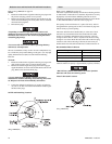
Regulator Adjustment Procedure:
Refer to Dwg. MHP2416 on page 48.
1. Attach test load of desired weight to load line, or connect
load line to scale.
• Ensure load line is connected to load and excessive slack is
taken up before activating auxiliary valve. When activated,
auxiliary valve will automatically engage and winch will
operate at full speed to set tension on load line.
2. With winch control valve remove all slack from load line.
Setting with test load:
1. Actuate auxiliary valve to TENSIONING position. Winch
should operate, causing load line to become taut. To increase
tension, turn regulator knob clockwise until load begins to
rise. Turn regulator knob counterclockwise a minimum of ¼
turn, or until load is balanced (does not raise or lower). Note
pressure indicated on gauge for future setting reference.
Setting with scale:
1. Actuate auxiliary valve to TENSIONING position. Winch
should operate, causing load line to become taut. To increase
tension, turn regulator knob clockwise until scale indicates
desired tension. Note pressure indicated on gauge for future
setting reference.
Disassembly
General Disassembly Instructions
The following instructions provide the necessary information to
disassemble, inspect, repair, and assemble the winch. Parts
drawings are provided in the Parts Section.
If a winch is being completely disassembled for any reason, follow
the order of the topics as they are presented. It is recommended
that all maintenance work on the winch be performed in a clean
dust free work area.
In the process of disassembling the winch, observe the following:
1. Never disassemble the winch any further than is necessary to
accomplish the needed repair. A good part can be damaged
during the course of disassembly.
2. Never use excessive force when removing parts. Tapping
gently around the perimeter of a cover or housing with a soft
hammer, for example, is sufficient to break the seal.
3. Do not heat a part with a flame to free it for removal, unless
the part being heated is already worn or damaged beyond
repair and no additional damage will occur to other parts.
In general, the winch is designed to permit easy disassembly and
assembly. The use of heat or excessive force should not be
required.
4. Keep the work area as clean as practical, to prevent dirt and
other foreign matter from getting into bearings or other
moving parts.
5. All seals and ‘O’ rings should be discarded once they have
been removed. New seals and ‘O’ rings should be used when
assembling the winch.
6. When grasping a part in a vise, always use leather-covered or
copper-covered vise jaws to protect the surface of the part
and help prevent distortion. This is particularly true of
threaded members, machined surfaces and housings.
7. Do not remove any part which is a press fit in or on a
subassembly unless the removal of that part is necessary for
repairs or replacement.
8. When removing ball bearings from shafts, it is best to use a
bearing puller. When removing bearings from housings, drive
out the bearing with a sleeve slightly smaller than the outside
diameter of the bearing. The end of the sleeve or pipe which
contacts the bearing must be square. Protect bearings from
dirt by keeping them wrapped in clean cloths.
Thermoplastic Coated Parts Disassembly
Thermoplastic coating on capscrew heads, nuts, housings and
other components can be removed as follows:
CAUTION
• Separate parts using proper tools. Ensure machined surfaces
are not damaged during disassembly.
1. Fasteners:
a. Push tool into or over fastener, forcing coating off of the
fastener.
b. If coating is too thick, then heat the fastener to soften
coating. Socket or wrench will push softened coating
off, allowing removal of part.
c. For socket head capscrews, setscrews, etc., heat the
component until coating is softened. Use a small
screwdriver or similar tool to remove coating to allow
access for wrench.
2. For housings, plates and other coated mating components use
a sharp knife or similar tool to cut through coating around
mating area of components.
Drum Guard Disassembly (optional feature)
Refer to Dwg. MHP0658 on page 62.
1. Remove capscrews (592).
2. Remove brackets (591) or (595) by sliding out of drum guard
(590).
3. Remove ‘O’ rings (109) and discard.
4. Carefully remove drum guard (590) from rear (drum brake
side) side rail (65). The drum guard attaches to side rail using
tabs. The smaller, upper tabs are visible on top of the side
rail. The longer, lower tab is located beneath side rail edge.
During removal care must be taken not to bend tabs. To
correctly remove, at the point where drum guard and side rail
meet, push or tap lower portion of drum guard in towards
winch drum (62). The direction of force should be directly
away from side rail. Do not pull up or down as tabs may
become deformed.
Winch Disassembly
Refer to Dwgs. MHP0649 on page 38 and MHP0690 on page 40.
1. Remove the wire rope from the drum. Remove wire rope
anchor (63) and store for reassembly.
2. Relieve pressure in air lines and winch air components by
operating winch control several times after air supply has
been turned off.
WARNING
• Shut off, bleed down and disconnect air supply line before
performing any disassembly procedures.