


32 MHD56087 - Edition 4
REVIEW COPY 6
-
21
-
02
• Do not rotate reverse valve past a 90 degree position, it may
result in the ball (916) falling in motor.
5. Slowly push reverse valve, while still in the 45 degree
position, the rest of the way in housing until flush with
surface. From other side of valve rotate reverse valve back to
neutral position, ball should be seated in ball slot at that time.
6. Lubricate ‘O’ ring (942) and place it in groove in exhaust
flange (955).
7. Secure exhaust flange (955) to valve housing with capscrews
(901) and washers (902).
8. Insert ‘O’ ring (941) into seal bracket (939). Lubricate ‘O’
ring (942) and place into groove in seal bracket.
9. Place seal bracket over end of reverse valve. Using finger
pressure, press until seal is seated on reverse valve and seal
bracket is seated on valve housing. Secure with washers
(924) and capscrews (925) and (938).
Pilot Valve Assembly
• For easier installation it is recommended to use I-R pilot seat
tool (920). This must be purchased separately. Operation of
this tool (920) is similar to an allen wrench or screw driver.
1. Install pilot valve assembly (910).
2. Apply thread sealant Loctite 567
® to pilot seat (914), place
pilot valve assembly into valve housing. Use a large flat
tipped screw driver to engage slots in pilot seat and tighten
until pilot assembly is 1/8 in. (3.175 mm) from housing bore.
3. Insert plug (912) and tighten.
Piston Assembly
1. Lubricate and install ‘O’ rings (921) and (923) on piston
(922).
2. Insert assembled piston into valve housing (917) from handle
side.
3. Secure with gasket (918), piston cover (919), washers (902)
and capscrews (901).
4. Place poppet seal (907) into poppet cap (906). Place this
assembly into valve housing and seat on piston (922).
5. Place spring (905) over this assembly.
6. Secure with gasket (904), poppet cover (903), washers (902)
and capscrews (901).
Handle Assembly
1. Place spring (937) over reverse valve handle end in seal
bracket.
• Spring (937) will have to be ‘Cocked’ over stud in seal
bracket. This will ensure handle returns to neutral.
2. Place handle assembly over reverse valve end. Slide handle
will have to be lifted slightly to allow pin to fit into slot in
seal bracket.
3. Secure handle assembly (930) to reverse valve with tab lock
washer (909) and capscrew (901), torque to 15 ft. lbs. (21
Nm). Washer (909) has small tab on side, engage with small
hole in handle.
4. Bend tabs of washer (909) over flats of capscrew.
5. Press plug (935) into handle assembly to cover capscrew.
Check control handle movement. Correct any discrepancies.
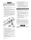
K5C2-EX Control Valve Assembly
Refer to Dwg. MHP2434 on page 50.
Reverse Valve Assembly
1. Insert reverse valve (943) into bushing (944) with ball slot
oriented UP. Apply grease to ball (916) and insert into ball
slot of reverse valve (943) through bushing (944).
2. Insert bushing (944), reverse valve (943) and ball (916) into
valve housing (917) from exhaust flange side, ensuring that
groove in bushing is aligned with pin (945).
3. Lubricate ‘O’ rings (942) and (722), and place in grooves in
exhaust adapter (723).
4. Lubricate ‘O’ rings (942) and place in grooves in exhaust
flange (955).
5. Secure exhaust adapter with exhaust flange to valve housing
with capscrews (721) and washers (902).
6. Insert ‘O’ ring (941) into seal bracket (939). Lubricate ‘O’
ring (942) and place into groove in seal bracket.
7. Place seal bracket over end of reverse valve. Using finger
pressure, press until seal is seated on reverse valve and seal
bracket is seated on valve housing. Secure with washers
(924) and capscrews (925) and (938).
Pilot Valve Assembly
Follow assembly instructions for K5C2-X Control Valve.
Piston Assembly
Follow assembly instructions for K5C2-X Control Valve.
Handle Assembly
Follow assembly instructions for K5C2-X Control Valve.
Emergency Stop Assembly
1. Insert spring (711) into valve housing (917).
2. Place ‘O’ rings (703) on plunger (707).
3. Insert plunger into valve housing.
4. Screw adapter (706) and E-Stop button (705) into valve
housing.
5. Tighten adapter until snug, do not over tighten.
Overload Valve Assembly
1. Replace ‘O’ rings (703) on plunger (702).
2. Insert plunger (702) with ‘O’ rings in valve housing (917).
3. Replace grommet (701) in cap (700).
4. Install and tighten cap (700) flush to valve housing.
5. Replace piston (712) if appears damaged or worn.
6. Insert ‘O’ ring (713) on piston (712).
7. Replace gasket (714).