


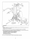
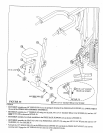

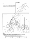
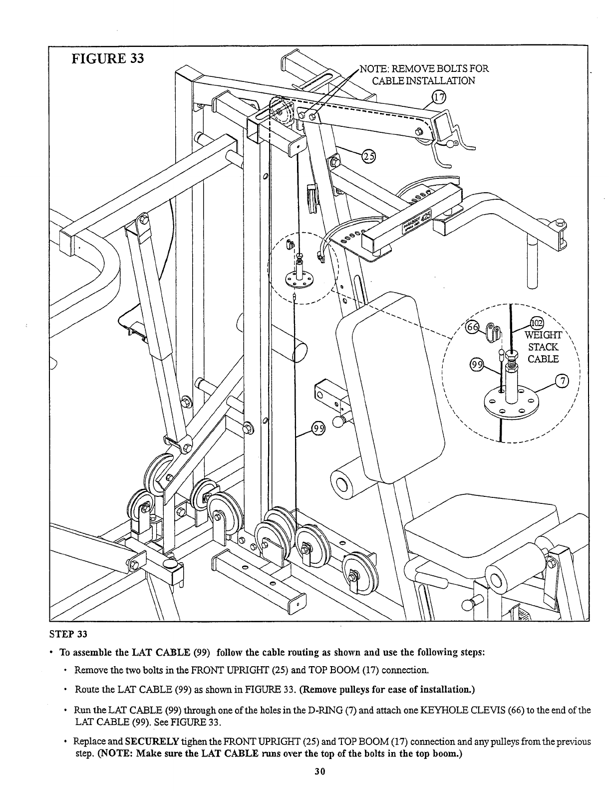
FIGURE 33
,NOTE: REMOVE BOLTS FOR
CABLE INSTALLATION
STEP 33
¯ To assemble the LAT CABLE (99) follow the cable routing as shown and use the following steps:
¯ Remove the two bolts in the FRONT UPRIGHT (25) and TOP BOOM (17) connection.
¯
Route the LAT CABLE (99) as shown in FIGURE 33. (Remove pulleys for ease of installation.)
¯
Run the LAT CABLE (99) through one of the holes in the D-RING (7) and attach one KEYHOLE CLEVIS (66) to the end
LAT CABLE (99). See FIGURE 33.
¯ Replace and SECURELY tighen the FRONT UPRIGHT (25) and TOP BOOM (17) connection and any pulleys fromthe prexdous
step. (NOTE: Make sure the LAT CABLE runs over the top of the bolts in the top boom.)
30