


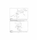
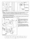
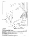

FIGURE 25
STEP 2S
¯
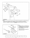
SECURELY assemble one 3/8" X 1" BUTTON HEAD CAP SCREW (96) and one 3/8" LOCK NUT (92) to the last hole on
BACK PAD ADfUST (16). See FIGURE 25.
¯
SECURELY insert one 2" SQ. END CAP (46) to the open end of*he BACK PAD ADJUST (16). See FIGURE
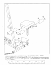
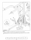
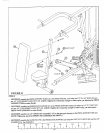
¯ SECURELY tighten all loose frame connections made to this point. (:!! EVIPORTANT !!! to assure proper function of the 425,
the loose frame connections.must be tightened in the following order) Tighten the:
¯ MIDDLE UPRIGHT (8) to the BASE (1) and to the TOP BOOM (17).
¯ REAR UPRIGHT (4) to *he BASE (1) and to the TOP BOOM (17).
¯ PRESS BASE (18) to *he REAR (4) and MIDDLE UPRIGHTS
¯ PRESS BASE (18) to *he BASE (1).
¯
FRONT UPRIGHT (25) to the BASE (1).
NOTE: DO NOT TIGI~ITEN T]ffE FRONT UPRIGHT TO TtIE TOP BOOM AT Ti~IR TIME.
22