


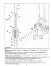
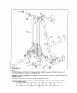
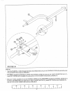
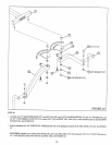
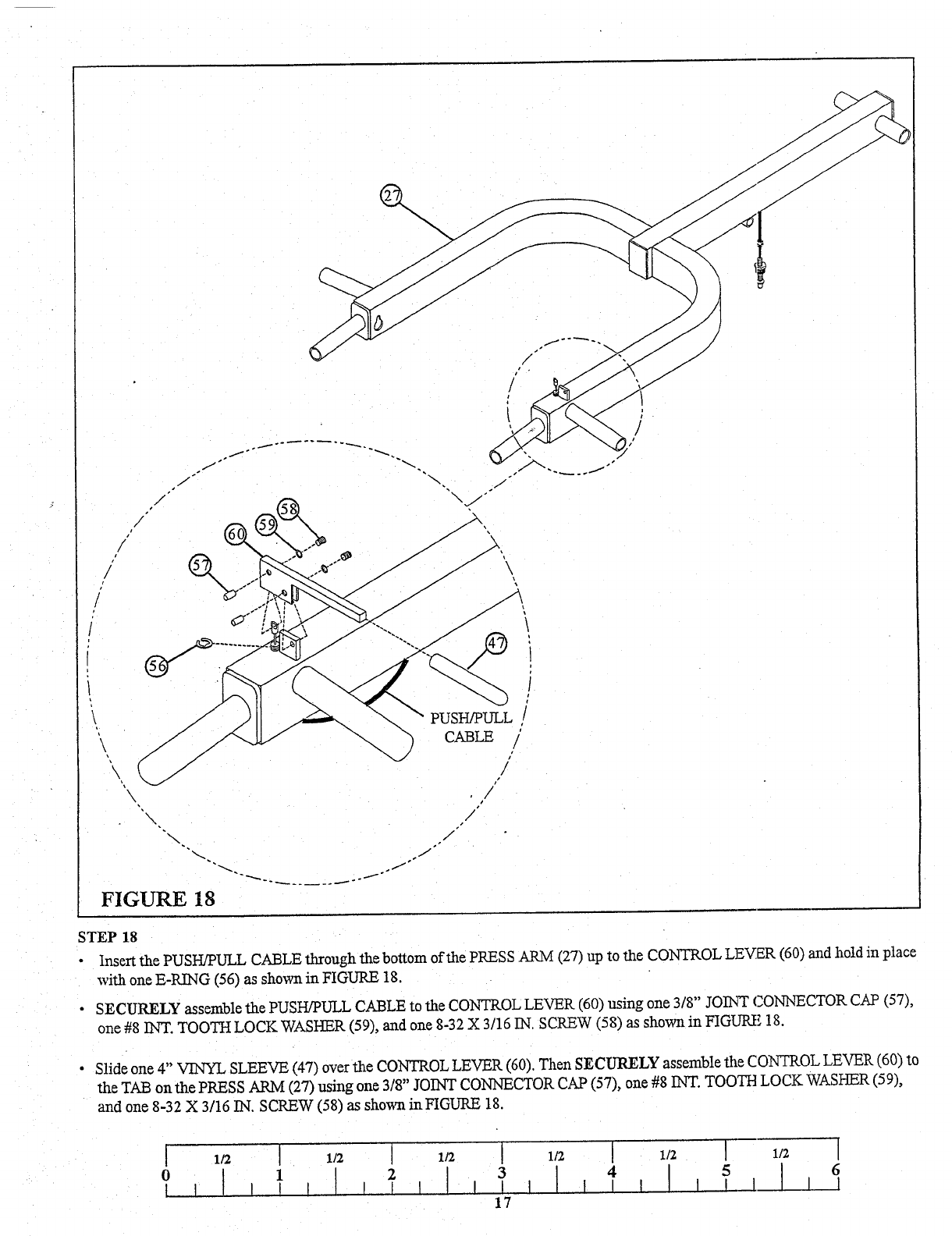
FIGURE 18
STEP 18
¯ Insert the PUSH/PULL CABLE through the bottom of the PRESS ARM (27) up to the CONTROL LEVER (60) and hold in place
with one E-RING (56) as shown in FIGURE 18.
¯ SECURELY assemble the PUSH/PULL CABLE to the CONTROL LEVER (60) using one 3/8" JOINT CONNECTOR CAP (57),
one #8 INT. TOOTH LOCK WASHER (59), and one 8-32 X 3/15 IN. SCREW (58) as shown in FIGURE
Slide one 4" VINYL SLEEVE (47) over the CONTROL LEVER (60). Then SECURELY assemble the CONTROL LEVER (60)
the TAB on the PRESS ARM (27) using one 3/8" JOINT CONNECTOR CAP (57), one #8 INT. TOOTH LOCK WASHER (59),
and one 8-32 X 3/16 IN. SCREW (58) as sho~a in FIGURE 18.
1/2
[
1/2 [
1/2 [ 1/2 [
1/2 ]
1/2 [
6
3
4
] I I__1
1
] I I I
¯
[ I I
I
17