


/~UTr
3/8X 1
’’
ONI-ID
SCREW
\
d~UT
LOW
IGHT
/
/
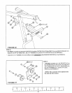
1/2 X 3-1/2",
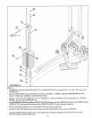
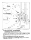
FIGURE 20
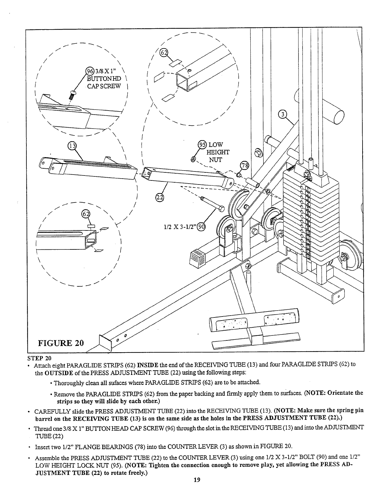
STEP 20
¯
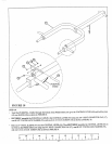
Attach eight PARAGLIDE STRIPS (62) INSIDE the end of the RECEIVING TUBE (13) and four PARAGLIDE STRIPS (62)
the OUTSIDE of the PRESS ADJUSTMENT TUBE (22) using the following steps:
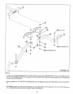
¯
Thoroughly clean all sufaces where PARAGLIDE STRIPS (62) are to be attached.
¯ Remove the PARAGLIDE STRIPS (62) from the paper backing and flrlnly apply them to surfaces. (NOTE: Orientate
strips so they will slide by each other.)
¯
CAREFULLY slide the PRESS ADJUSTMENT TUBE (22) into the RECEIVING TUBE (13). (NOTE: Make sure the spring
barrel on the RECEIVING TUBE (13) is on the same side as the holes in the PRESS ADJUSTMENT TUBE (22).)
¯ Thread one 3/8 X 1" BUTTON HEAD CAP SCREW (96) throughthe slot in the RECEIVING TUBE (13) and into the ADJUSTMENT
TUBE (22)
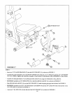
¯ Insert two 1/2" FLANGE BEARINGS (78) into the COUNTER LEVER (3) as shown in FIGURE
¯
Assemble the PRESS ADJUSTMENT TUBE (22) to the COUNTER LEVER (3) using one 1/2 X 3-1/2" BOLT (90) and one
LOW HEIGHT LOCK NUT (95). (NOTE: Tighten the connection enough to remove play, yet allowing the PRESS
JUSTMENT TUBE (22) to rotate freely.)
19