5 - 62 FUNCTION REFERENCE
SCREEN CONTROLS AND GRATICULE
Description:
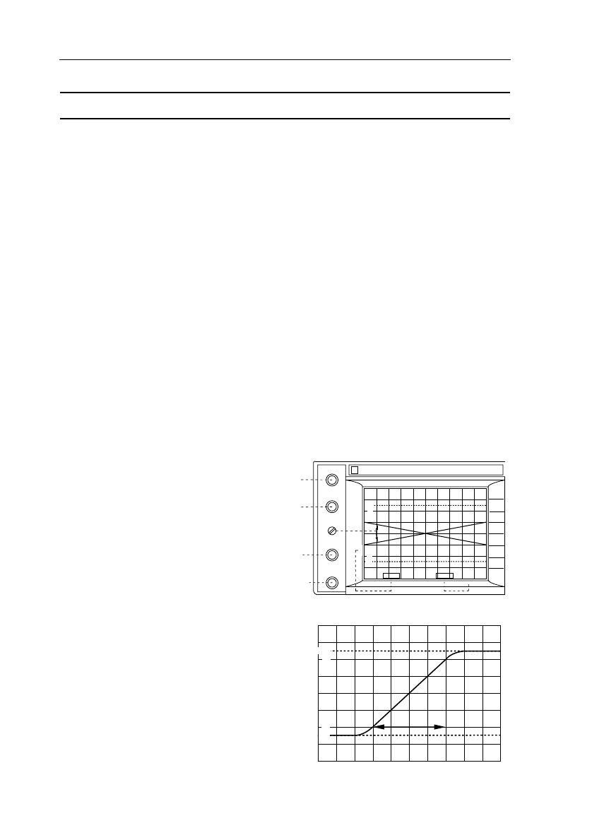
The screen controls are located to the left of the CRT viewing area.
Brightness of trace(s) and text can be adjusted separately with the TRACE
INTENSITY and TEXT INTENSITY controls. Intensity of the trace(s) can also be
determined by a voltage applied to the rear panel socket Z MOD. Refer to
’Characteristics’ Chapter 1 of the Reference Manual for input amplitudes.
The FOCUS control is used to optimize display sharpness.
A graticule is a provided with 1cm x 1cm divisions. Each vertical centimeter
equals the indicated channel sensitivity. A horizontal centimeter equals the
indicated timebase setting. The graticule has 0, 10, 90, and 100 % lines that can
be used for risetime measurements. For these, the signal peaks are exactly
positioned on the 0 and 100 % lines. The risetime of the pulse is readout between
the 10 and 90 % lines as shown in the following figure. Intensity of graticule
illumination is controlled with the GRATICULE ILLUMINATION control.
Trace alignment is done with the screwdriver operated TRACE ROTATION control.
TRACE
INTENSITY
TEXT
INTENSITY
TRACE
ROTATION
FOCUS
GRATICULE
ILLUMINATION
TRACE
BRILLIANCE
TEXT
BRILLIANCE
DISPLAY
SHARPNESS
GRATICULE
ILLUMINATION
CH1
20mV
MTB
0.2ms
}
{
MAT4216
9303
100
90
10
0%
Screen controls and function of
TRACE ROTATION.
MAT4217
RISE
TIME
100
90
10
0%
Rise time measurement using the graticule.


