Groundsmaster 4000--D Page 5 -- 31 Electrical System
Fusible Link Harness
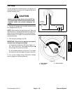
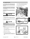
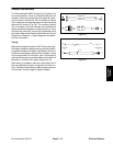
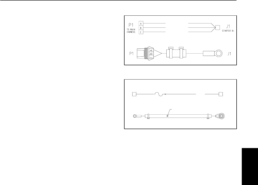
The Groundsmaster 4000--D uses five (5) fusible links
for circuit protection. Three (3) of these fusible links are
located in a harness that connects the starter B+ termi-
nal to the wire harness (Fig. 49). An additional fusible
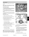
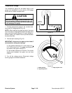
link is used that connects the starter B+ terminal to the
alternator B+ terminal (Fig. 50). The remaining fusible
link is included in the wire harness and connects the
starter terminal to the engine run solenoid pull coil. If any
of these links should fail, current to the protected circuit
will cease. Refer to the Electrical Schematic and Circuit
Diagrams in Chapter 9 -- Foldout Diagrams for addition-
al circuit information.
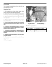
Testing
Make sure that ignition switch is OFF. Disconnect nega-
tive battery cable from battery terminal and then discon-
nect positive cable from battery (see Battery Service in
the Service and Repairs section of this chapter). Locate
and unplug fusible link connector. Use a multimeter to
make sure that continuity exists between the fusible link
terminals. If a fusible link is open, replace the link.
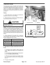
After testing is complete, make sure that fusible link is
securely attached to engine component and wire har-
ness. Connect positive battery cable to battery terminal
first and then connect negative cable to battery.
Figure 49
FUSIBLE LINK
FUSIBLE LINK
FUSIBLE LINK
Figure 50
RED
SP1
B+
STARTER ALTERNATOR
B+
J1
J2
J1 J2
SP1
Electrical
System


