Groundsmaster 4000--D Page 5 -- 11 Electrical System
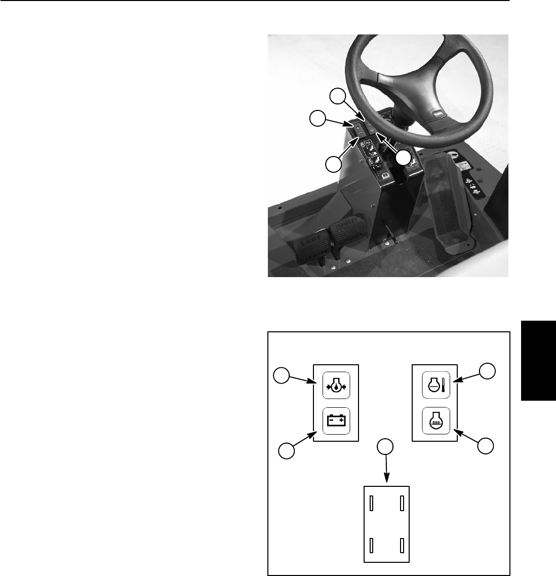
Warning Lights
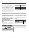
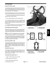
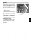
Engine Oil Pressure Light
The oil pressure lightshould illuminatewhen the ignition
switch is in the ON position with the engine not running.
Also, itshouldlightwiththe engine running if the oilpres-
sure drops below 7 PSI (0.5 kg/cm
2
).
If oil pressure light does not come on when the ignition
switch is in the ON position with the engine not running:
1. Locate oil pressure switch on engine and disconnect
green harness wire from switch.
2. Ground disconnected wire to the engine block.
3. Turn ignition switch to ON; the oil pressure light
should illuminate indicating correct operation of the
electrical circuit between the oil pressure switch and oil
pressure light.
4. Turn ignition switch OFF and connect harness wire
to oil pressure switch after testing is complete.
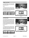
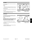
High Temperature Warning Light
If the coolant temperature rises to approximately 220
o
F
(105
o
C), the high temperature warning light should illu-
minate as the dual temperature switch terminal closes.
NOTE: If the PTO is engaged when the dual tempera-
ture switch terminal closes, the PTO will disengage.
To test the high temperature warning light and its circuit
wiring, ground the blue wire attached to dual tempera-
ture switch on engine water flange. The high tempera-
ture warning light should illuminate.
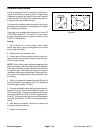
Glow Plug Indicator Light
The glow plug indicator light should illuminate when the
ignitionswitchis placedinON priortoplacing theignition
switch in START. The light should stay lit for approxi-
mately 10 seconds while the ignition switch is left in the
ON position.
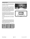
Charge Indicator Light
The charge indicator light should illuminate when the
ignition switch is theONpositionwith the engine not run-
ning or with an improperly operating charging circuit
while the engine is running.
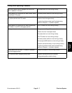
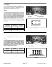
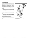
Testing Warning Lights (Fig. 12)
1. Apply 12 VDC to terminals 1A and 2A.
2. Ground terminals 1B and 2B.
3. Both indicator lights should light.
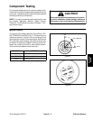
1. Charge indicator
2. Engine oil pressure
3. High temp shutdown
4. Glow plug indicator
Figure 11
1
2
3
4
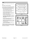
Figure 12
1. Charge indicator
2. Engine oil pressure
3. High temp shutdown
4. Glow plug indicator
5. Warning light back
1A
2A2B
1B
1
2
3
4
5
Electrical
System


