Rev. A
Groundsmaster 4000--D Page 5 -- 27 Electrical System
Dual Temperature Switch
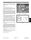
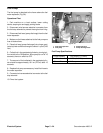
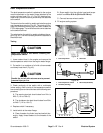
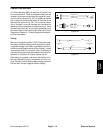
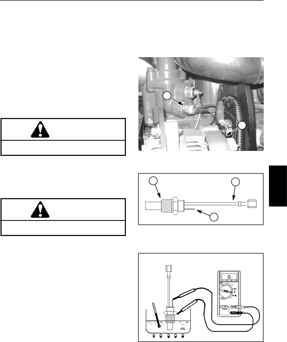
The dual temperature switch is attached to the engine
near the alternator on the water flange attached to the
engine cylinder head (Fig. 41). Two (2) electrical har-
ness wires (a blue wire and a yellow wire) are attached
to the switch.
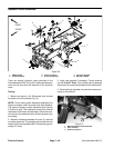
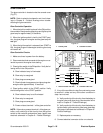
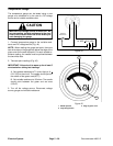
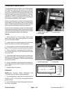
The terminal on the switch is used to activate the engine
over temperature warning (Fig. 42). The warning illumi-
nates the overtemp warning light and also causes the
PTO to disengage. The wire harness blue wire attaches
to the switch terminal.
The wire lead on the switch is used to shutdown the en-
gine (Fig. 42). The wire harness yellow wire attaches to
the switch lead.
Testing
CAUTION
Make sure engine is cool before removi ng the
temperature switch.
1. Lower coolant level in the engine and remove the
dual temperature switch from the engine water flange.
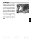
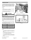
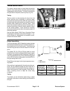
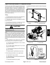
2. Put switch in a container of oil with a thermometer
and slowly heat the oil (Fig. 43).
CAUTION
Handle the hot oil with extreme care to prevent
personal injury or fire.
3. Check continuity of the switch with a multimeter
(ohms setting). Both circuits of the temperature switch
are normally open and should close at the following tem-
peratures:
A. The warning terminal should close from 214
o
to
226
o
F (101 to 108
o
C).
B. The shutdown wire lead should close from 234
o
to 246
o
F(112to119
o
C).
4. Replace switch if necessary.
5. Install switch to the water flange.
A. Clean threads of cylinder head and switch thor-
oughly. Apply thread sealant to the threads of the
switch.
B. Screw switch into the cylinder head and torque
switch from 22 to 28 ft --lb (29.4 to 39.2 N--m).
C. Connect harness wires to switch.
6. Fill engine cooling system.
1. Dual temp switch 2. Alternator
Figure 41
1
2
1. Dual temperature switch
2. Terminal (warning)
3. Wire lead (shutdown)
Figure 42
1
3
2
Figure 43
Electrical
System


