


22 Assembling and Maintaining TRM 800-Series Treadmills
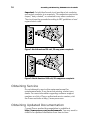
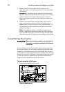
5. Remove the Auto Stop cable from the tube on the
right-hand side of the fairing (position 2 in the preceding
illustration).
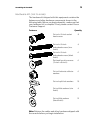
Important: In the following step, make sure that the end of
the data cable with the ferrite bead is the upper end. Likewise,
on the automatic stop sensor cable, the three-conductor
socket is the lower end and the four-conductor socket is the
upper end.
6. Remove any tape that secure the cables, then unwind
them and remove any kinks. Gather the cables into a
single bundle (referred to later as the cable assembly). Do
not remove the cable tie that secures the ferrite to the
cable to the frame.
Note: Arranging the cables so that the connectors are
slightly staggered at the bottom end (but still within one
inch or three centimeters overall) can help when feeding
the cable assembly through narrow openings in the frame.
Assembling the Frame
DANGER
Make sure that the treadmill is not connected to
any power source before you begin the following
procedures.
As you add the left-hand and right-hand upright supports to
the treadmill base, you will need to make sure that the cable
assembly is threaded properly through the left-hand support
so that the necessary connections are available when you add
the control console. A fish tape (a thin metal strip with a hook
or clasp on one end, available from professional hardware
vendors) can be helpful during this procedure.
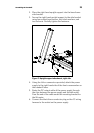
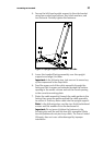
To begin assembly of the frame:
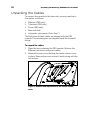
1. Remove the hood and set it aside.
Figure 6: Hood removal