


Cateye Ergociser Series 1000 Service Manual
37
EC-1200 EC-1600 EC-3600 EC-3700
Applicable Models:
MS-1
MS-1
Fig. 1
K 6020
I
mA
COIL
LOT No.
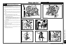
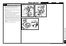
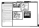
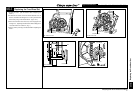
Replacing the Workload Unit (w/o Flywheel) (3)
Checking the Positions of Copper Disk Plate and Solenoid Coil
Core Slit
Regarding the workload unit, positions of copper disk plate
and solenoid coil core slit have been adjusted before
mounting the frame so that they will not touch each other
while the plate is rotating. However, due to positional
distortion caused by tightening the bolts while the frame is
being mounted, the copper disk plate may touch the core.
(Fig. 1)
Rotate the copper disk plate slowly to check if it does not
touch the core. If it does, it is necessary to eliminate the
positional distortion caused by the tightening.
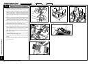
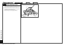
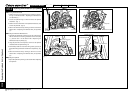
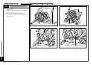
Correction Method
Correction can be made by tightening the frame-side nuts of the
workload reinforcing metal base. Tighten the metal base toward the
direction in which the positional correction of the copper disk plate
should be made, until the plate comes close to the center of the core
slit (Fig. 1). (See the Section ES-4 "Correcting the Position of
Solenoid Coil.")
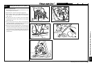
1. After checking the correction direction, use a wrench to tighten
the frame-side nut of the workload unit reinforcing metal base.
Give the even tightening to both right and left sides.
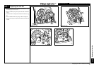
2. As shown in Fig. 2, set a cable for measuring coil current in
between the CN-1 female connector and the CN-1 male
connector at the side of power supply board, and connect the
cable to an ammeter.
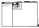
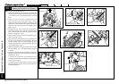
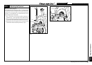
3. Turn on the power switch of the main unit, set the control unit
to the manual mode, select the torque at 4.0kg·m, and start the
system.
4. Using a blade-head screwdriver, adjust the potentiometer on
the power supply board so that the meter reading shows the
coil current which is specified on the solenoid coil of the
workload unit.
Example:As shown in Fig. 3, when 630 is indicated, adjust the
potentiometer so that the coil current will be 630mA.
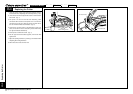
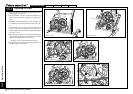
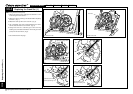
5. After having adjusted the coil current, remove the measuring
cable, and connect the female connector of the CN-1 cable
directly to the male connector at the power supply board side.
6. Fix the cable onto the seat pipe with cable holders.
Adjusting the Flywheel
1. Adjust the flywheel by referring to the Section MS-3 "Adjusting
the Flywheel."
Correct Position
Copper Disk Plate
Core
Core Slit
Fig. 2
Frame-Side Nut
Workload-Unit-Side Nut
Fig. 3
Power Supply Board
CN-1 Connector
CN-1 Female
Connector
Cable for Measuring
Coil Current
Fig. 4
Replacing the Workload Unit (w/o Flywheel) (3)
Workload Unit
Reinforcing Metal Base