


Check Method of Causes Repair Method Explanation Figures
EC-1200 EC-1600 EC-3600 EC-3700
Applicable Models:
Cateye Ergociser Series 1000 Service Manual
11
T-1
T-1
Black Cable
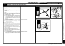
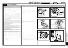
No Display on Control Unit after Power ON. (1)
Check the power is available at the wall socket before proceeding to
checking of causes.
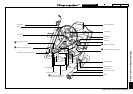
[1] Checking the AC Adapter
1. Detach the plug of AC adapter from the AC adapter inlet of the
main unit.
2. Connect the wall socket plug of the AC adapter to the wall
socket.
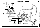
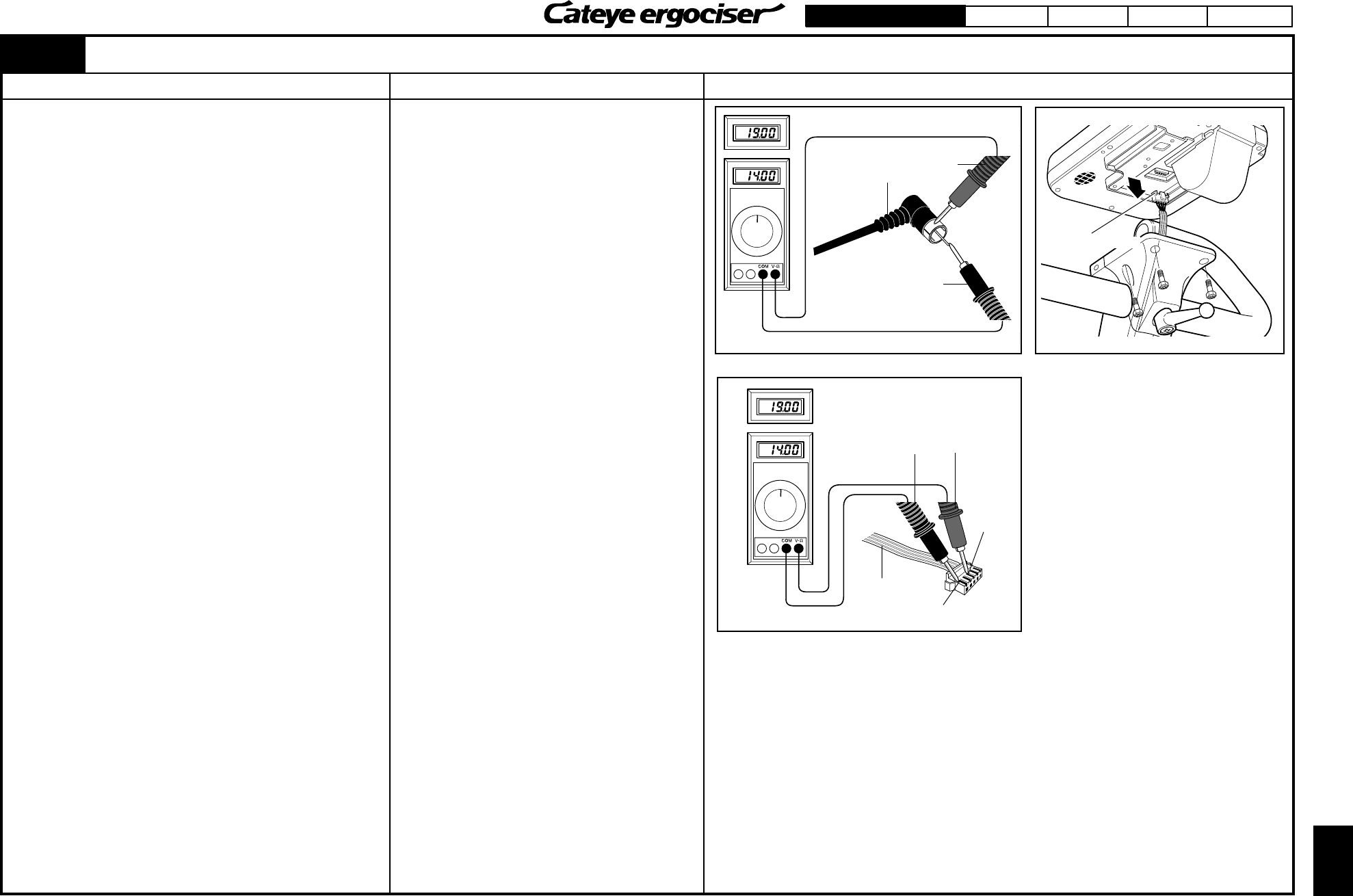
3. Using a tester, measure the voltage at the plug which will be
connected to the main unit. (Fig. 1)
The AC adapter will be working fine, if the voltage is minus
(-) at the inner area and plus (+) at the outer area of the
connector and also the meter reading is in the range of 14V
and 19V.
When the measured voltage is 0V, or less than 14V, the
AC adapter will be defective.
Note: Never short-circuit the plug of AC adapter. This will
damage the AC adapter.
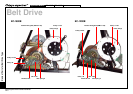
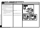
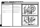
[2] Checking the Wiring within the Frame
1. When the AC adapter is found to be correct, proceed to
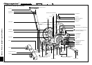
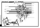
checking of wiring within the frame. Loosen the four screws
on the handlebar stem to remove the control unit. (Fig. 2)
2. Remove the 5P cable which is connected to the back of the
control unit. (Fig. 2)
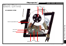
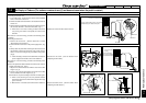
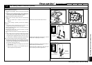
3. Connect the AC adapter, and turn on the main unit.
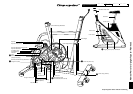
4. Using a tester, measure the voltage across the terminals 1 (-)
and 3 (+) of the 5P cable. (Fig. 3)
The main unit side will be working fine if the meter reading
is in the range of 14V and 19V. This means the control unit
will be defective.
Fig. 1
Normal for 14V thru 19V
Red Cable
DC Connector
Fig. 2
Cable Connector
Fig. 3
Normal for 14V thru 19V
Black Cable
Red Cable
5P Cable
Terminal 1 (-)
No Display on Control Unit after Power ON. (1)
Replace the AC adapter.
Replace the control unit.
Terminal
3 (+)