


Cateye Ergociser Series 1000 Service Manual
29
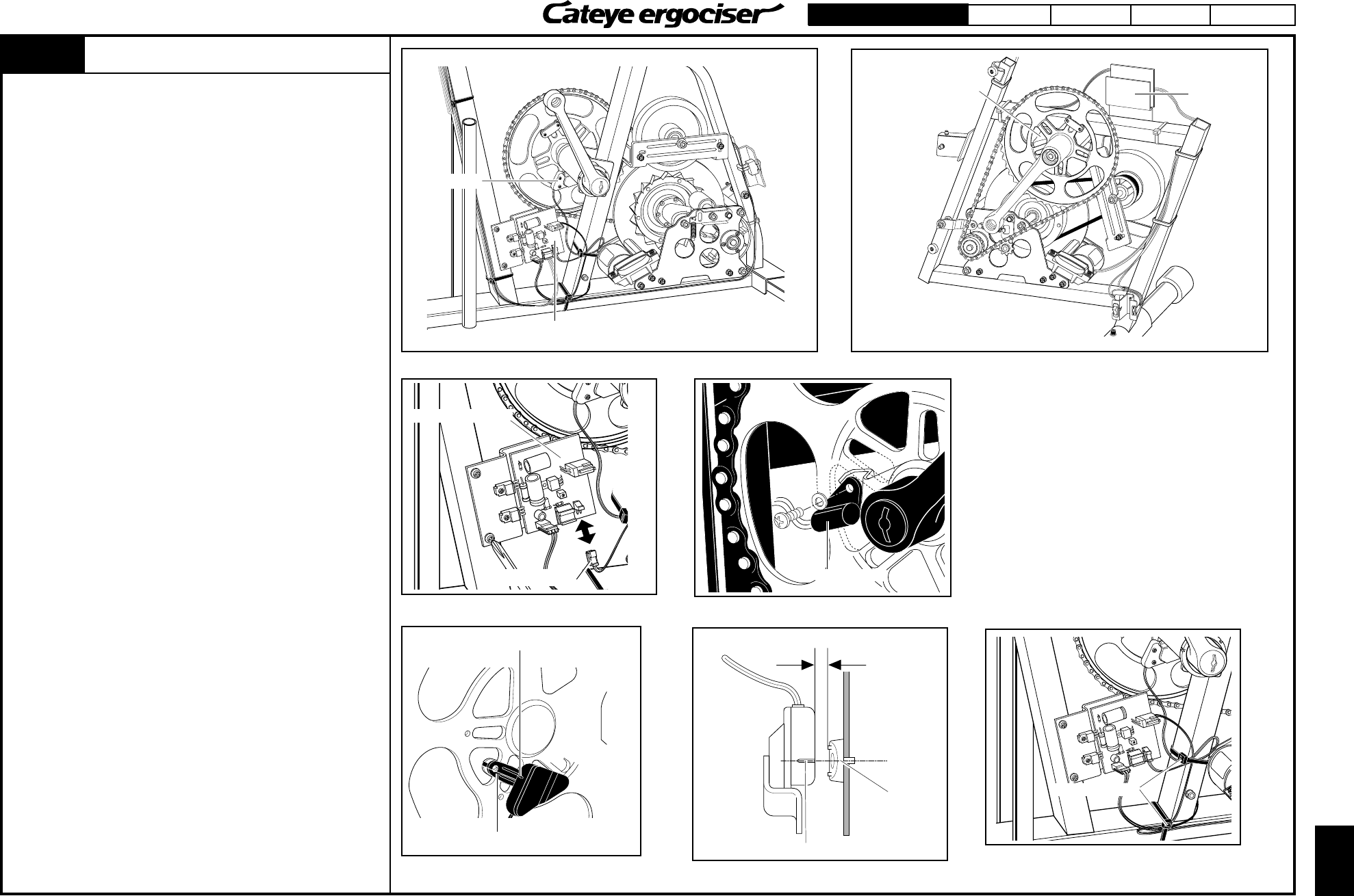
EC-1200 EC-1600 EC-3600 EC-3700
Applicable Models:
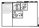
ON
OFF
ES-5
ES-5
CDC Sensor
CDC Sensor
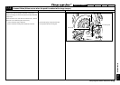
Power Supply Board
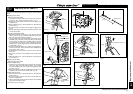
EC-1200 & EC-1600
Power Supply
Board
EC-3600 & EC-3700
Fig. 1
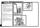
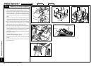
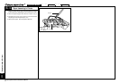
Power Supply Board
CN-3 Connector
Fig. 2
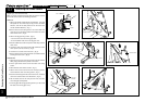
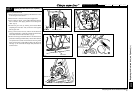
CDC Sensor
Line on CDC Sensor
Center of CDC Magnet
Fig. 3
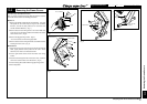
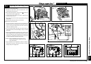
Approx. 2mm gap between CDC sensor and
CDC magnet
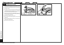
Center of CDC
Magnet
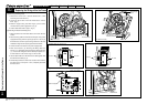
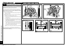
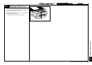
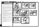
Cable Holders
Fig. 5
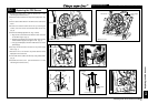
Replacing the CDC Sensor
1. Remove the frame cover. (See the Sections D-1 & D-2
"Removing the Frame Covers.")
2. Detach the CN-3 connector from the power supply board. (Fig.
1)
3. Cut the cable holders which fix the CDC sensor cable to the
frame.
4. Remove the defective CDC sensor set by loosening the
screws, and mount and fix the brandnew CDC sensor set.
(Fig. 2)
5. Perform the following adjustments. (Figs. 3 and 4)
Align the line on the CDC sensor with the center of the line
on the CDC magnet. (Fig. 3)
Adjust the gap between the surface of CDC sensor and the
surface of CDC magnet to be approx. 2mm. (Fig. 4)
* If the gap is inadequate, bend the metal base to secure the
specified gap.
6. Securely connect the CN-3 connector to the power supply
board. (Fig. 1)
7. Rotate the crank, and check if the pedal cadence will be
displayed on the control unit.
8. Fix the CDC sensor cable to the frame by using cable holders.
(Fig. 5)
9. Assemble the frame cover. (See the Sections D-1 & D-2
"Removing the Frame Covers.")
Replacing the CDC Sensor
Fig. 4
Line on CDC Sensor