


Cateye Ergociser Series 1000 Service Manual
27
EC-1200 EC-1600 EC-3600 EC-3700
Applicable Models:
Power Supply
Board
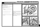
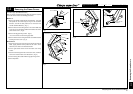
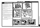
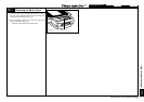
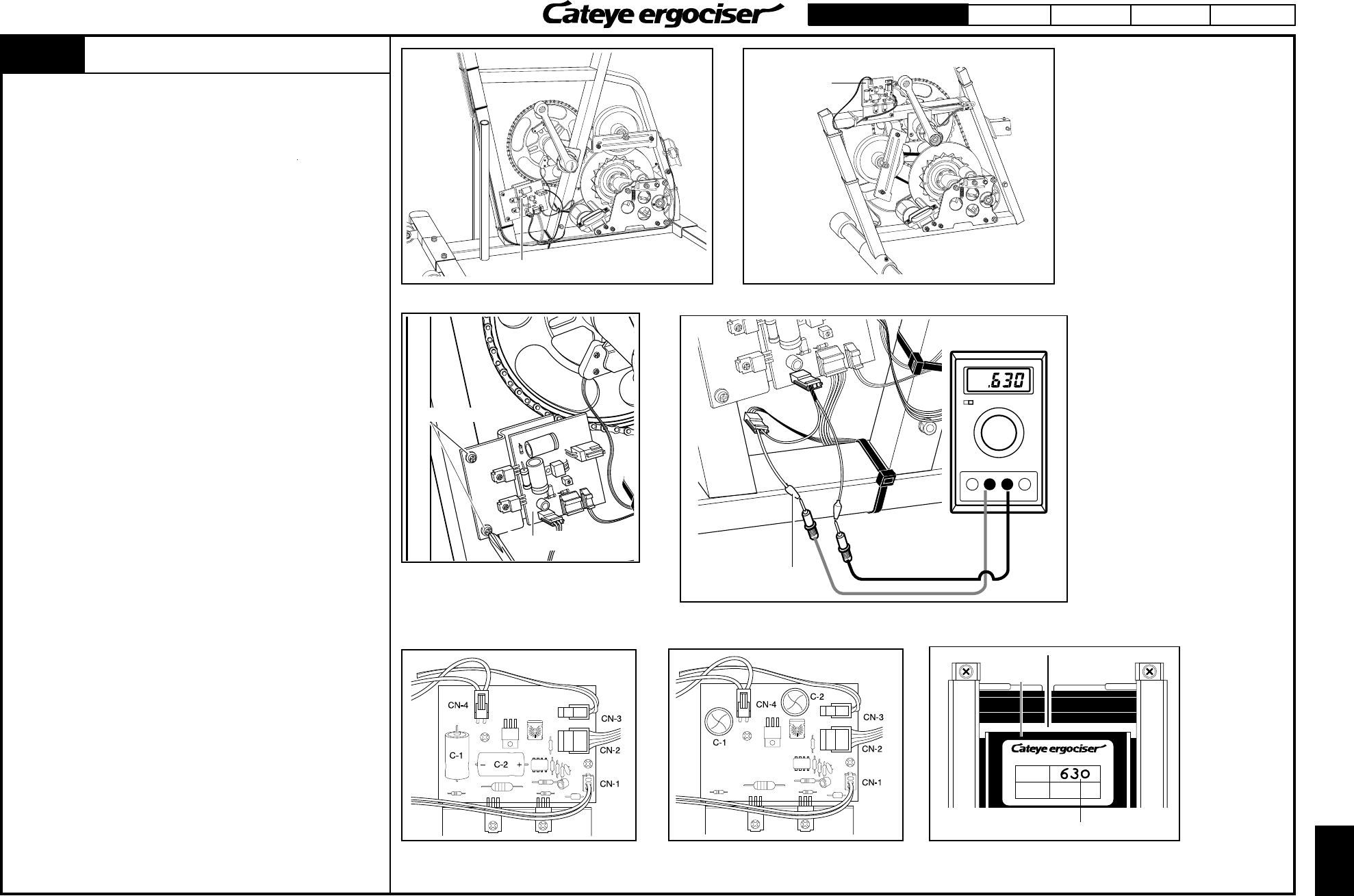
[1] Replacing the Power Supply Board
1. Remove the frame cover. (See the Sections D-1 & D-2
"Removing the Frame Covers.")
2. Remove all connectors CN-1, CN-2, CN-3 and CN-4 which are
connected to the power supply board.
3. Loosen the two screws which fix the power supply board to
remove the board. (Fig. 1)
4. Securely fix the brand new power supply board by using two
fixing screws.
5. Connect three connectors, CN-2, CN-3 and CN-4.
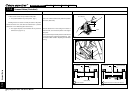
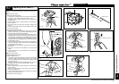
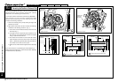
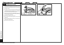
[2] Adjustment of Coil Current Value
1. Connect the cables for measuring coil current between the
female connector of the solenoid coil and the male connector
(CN-1) on the power supply board, and then connect the
cables to an ammeter. (Fig. 2)
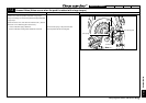
2. Turn on the power switch of the main unit, set the control unit
to the manual mode, set the load display to 4.0kg m, and start
the system.
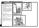
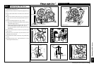
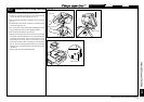
3. Adjust the potentiometer (as shown in Figs. 3 and 4) on the
power supply board with a blade-head screwdriver so that the
coil current will be the value indicated on the workload unit
solenoid coil. (A clockwise turn will increase the current, while
a counter-clockwise turn will reduce the current.)
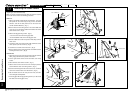
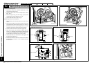
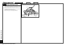
Example: When the indication is 630 as shown in Fig. 5,
adjust the potentiometer so that the coil current
value will be 630mA.
4. Upon completion of the adjustment, detach the cable for
measuring coil current, and connect the CN-1 connector
directly to the power supply board.
ES-3
ES-3
Replacing the Power Supply Board
Power Supply Board
EC-1200 & EC-1600
EC-3600 & EC-3700
Fig. 1
Fixing Screws
Power Supply Board
Fig. 2
Cable for Measuring
Coil Current
Fig. 3
Power Supply Board A
Fig. 4
Power Supply Board B
Fig. 5
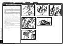
K
I
mA
COIL
LOT No.
Solenoid
Coil
Location of Coil Current Value Indication
Replacing the Power Supply Board