


Check Method of Causes Repair Method Explanation Figures
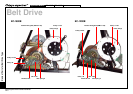
EC-1200 EC-1600 EC-3600 EC-3700
Applicable Models:
Cateye Ergociser Series 1000 Service Manual
12
T-1
T-1
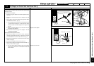
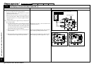
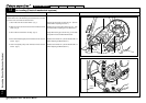
No Display on Control Unit after Power ON. (2)
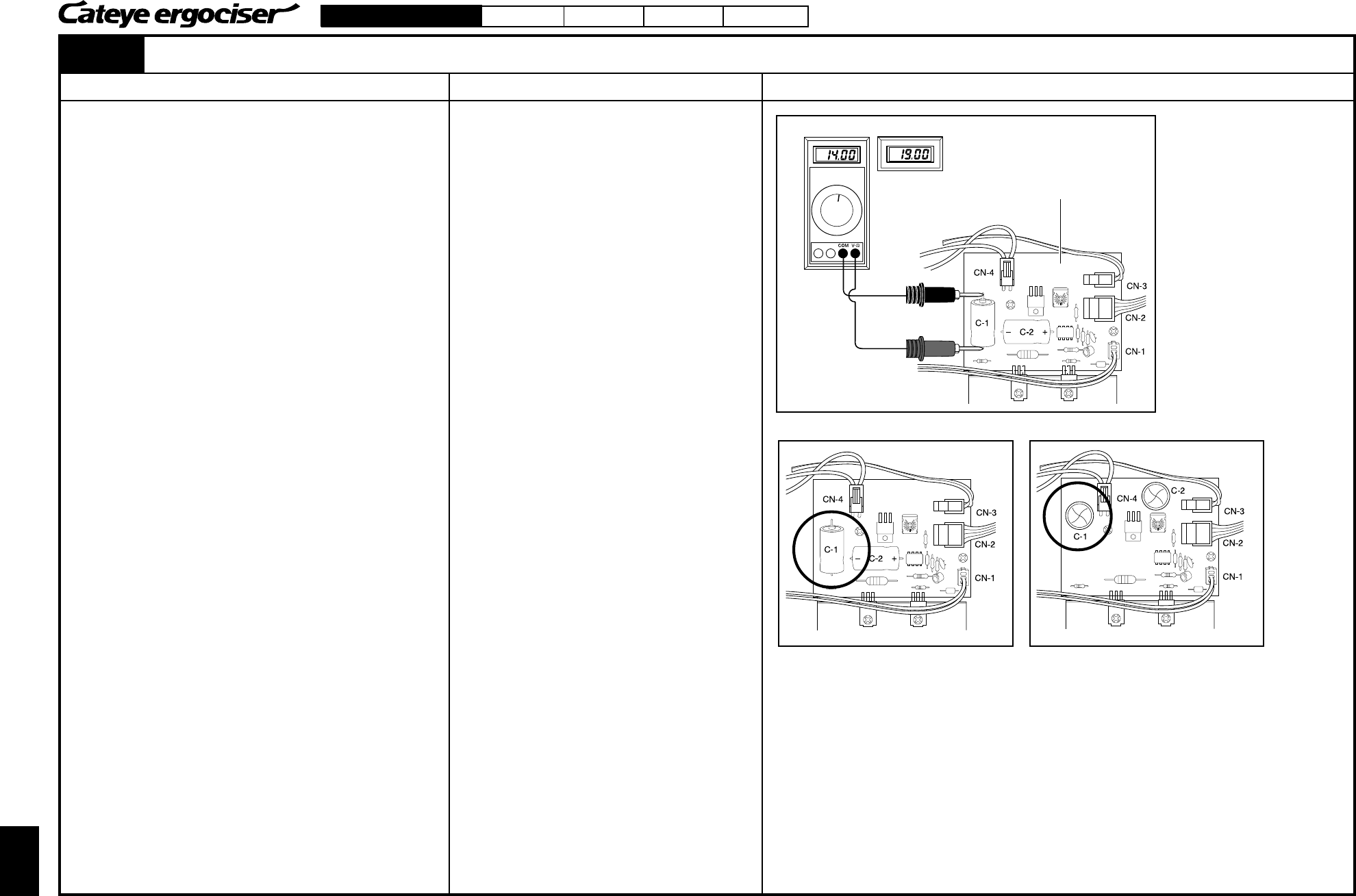
[3] When the meter reading at step 2. is 0V or less than 14V, check the
main unit in accordance with the following procedures:
1. Remove the frame cover. (See sections D-1 and D-2
"Removing the Frame Covers.")
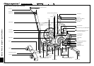
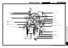
2. With the control unit removed, connect the AC adapter, and
turn on the power switch. Measure the voltage across the
electrolytic capacitor C1 on the power supply board (25V
1000µV). (Fig. 4)
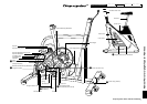
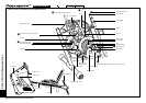
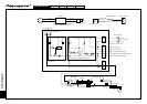
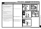
Note: The layout of the power supply board may be different from
lot to lot. (Figs. 5 and 6)
The wiring within the frame is correct when the measured
voltage is in the range of 14V and 19V. When the voltage
across the electrolytic capacitor on the power supply board
is correct, the 5P cable, which connects the power supply
board and the control unit, may be defective.
When the measured voltage is 0V, the wiring within the
frame is defective.
When the problem cannot be remedied even if the 5P cable
is replaced, the power supply board may be defective.
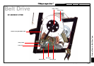
Fig. 4
Correct for 14V thru 19V
Power Supply Board
Black Cable
Red Cable
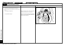
Fig. 5
Power Supply Board A
Fig. 6
Power Supply Board B
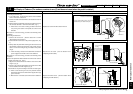
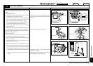
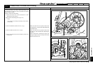
No Display on Control Unit after Power ON. (2)
Replace the 5P cable. (See the Section ES-2
"Replacing the Frame.")
Replace the Inlet Metal Base Set. (See the Section
ES-1 "Replacing the Wiring within the Frame."
Replace the power supply board. (See the Section
ES-3 "Replacing the Power Supply Board. "Fig. 4