


Cateye Ergociser Series 1000 Service Manual
26
EC-1200 EC-1600 EC-3600 EC-3700
Applicable Models:
ES-2
ES-2
EC-1600
30cm
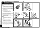
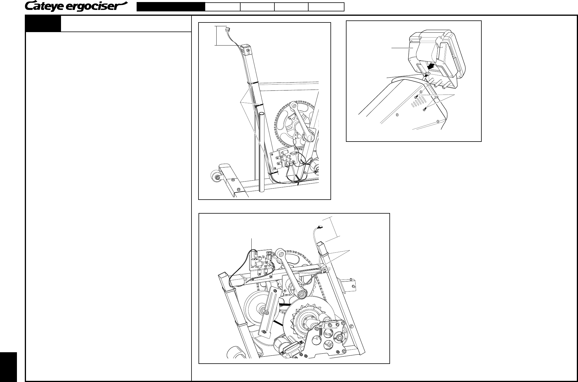
Replacing the 5P Cable (2)
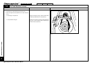
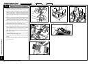
Mounting the Brand New Cable
5P Cable within the Handlebar Post
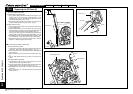
1. Using cable holders, bind the 5P cable, leaving approx. 5cm
portion from the control unit side cable connector, to the
handlebar post. (Fig. 7) Assemble the handlebar post cover
and the handlebar stem cover. (Fig. 6)
2. Connect the cable connector to the control unit, and fix the unit
to the handlebar post by using four screws. (Fig. 5)
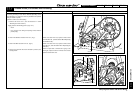
5P Cable within the Frame
1. Connect the CN-2 Connector at the end of the 5P cable to the
power supply board.
2. (1)Using cable holders, fix the 5P cable to the frame, leaving
the extra portion of 10cm from the top of the handlebar pipe.(2)
Fix the 5P cable at the bottom of the handlebar pipe.(3)
Pass the 5P cable along the handlebar pipe, and bind the
sagging portion to the point (3) by using cable holders. (Fig. 8)
3. Provisionally connect the intermediate cable connector, and
turn on the power. Then, check if the control unit works fine.
4. Mount the frame cover to restore the original shape. (See the
Section D-1 "Removing the Frame Covers.")
Recumbent Type (EC-3600 and EC-3700)
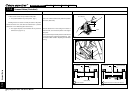
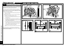
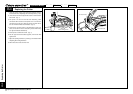
Removing the Existing Cable
1. Loosen the four screws which fix the control unit to remove the
control unit. Also, remove the cable connector. (Fig. 10)
2. Remove the frame cover. (See the Section D-2 "Removing the
Frame Covers.")
3. Remove the 5P connector from the power supply board. (Fig.
2)
4. Cut the cable holders which fix the cable to remove the 5P
cable.
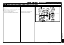
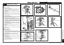
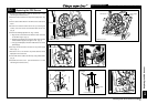
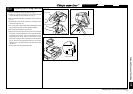
Mounting the Brand New Cable
1. Leaving approx. 30cm from the end of the frame, fix the 5P
cable to the frame by using cable holders.
2. Connect the 5P cable to the power supply board, and bind the
sagging portion to the point (2) of the frame. (Fig. 11)
3. Provisionally turn on the power, and check if the control unit
works fine.
4. Mount the frame cover. (See the Section D-2 "Removing the
Frame Covers.")
Fig. 9
Control Unit
5P Cable
Screws
Fig. 10
Cable Holders
Fig. 11
Power Supply Board
Cable Holders
Replacing the 5P Cable (2)
10cm
(1)
(3)
(2)